9-2
Calibration and Maintenance
NOTE –
All Veeco-provided calibration standards are certified by Physikalisch - Technische
Bundesanstat in Braunschweig., Germany, according to the European norm EN 5436-1 (Type
A-1). A certificate is included with each standard.
3
Make some preliminary measurements and to ensure that the standard is correctly positioned and that the
profile trace is in range.
4
Run an automation program provided by Veeco to perform five measurements, calculate an analytical
function, and average the results.
5
Compare the measured value with the certified value. The measured value should be within
± 0.5%
of the
certified value.
6
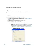
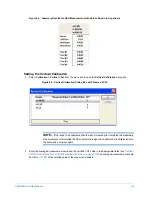
Enter the results of the averaged measurement in the
Vertical Calibration
dialog box.
7
Repeat the above steps to set the calibration for each additional measurement range.
CALIBRATING THE 65 KÅ RANGE
This section tells you how to set the calibration for the 65
kÅ
measurement range. The steps are
similar for the other measurement ranges.
Making the Preliminary Measurements
To make the preliminary measurements for the 65
kÅ range:
1
Place a 5
μ
m
(50
kÅ)
calibration standard on the center of the leveled stage.
2
Use the
Stage Control Panel
or move the sample itself
to position the sample under the stylus.
3
Select
Profiler
>
Tower Down
. The optical assembly towers down, the stylus nulls, and the stylus lifts off
the sample.
4
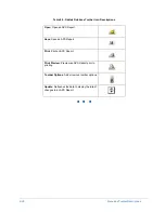
Adjust the illumination with either the
Illumination Up
and
Illumination Down
icons
or use the Up and Down Arrow keys on the keyboard.
5
Use the
Stage Control Panel
or move the sample itself
until the crosshairs are at the desired
measurement location.
NOTE –
Check the documentation that came with your standard to confirm the certified
measurement location (scan in the zone between the 2 scribe marks).
6
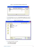
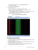
In the
Vertical Calibration
dialog box, clear the Vertical Calibration Factor (VCF)
BEFORE
the
measurement. To do this, select the desired range and click
Clear
. The VCF goes to 1.
Summary of Contents for Dektak 150
Page 1: ......
Page 7: ......
Page 17: ......
Page 81: ......
Page 105: ......
Page 149: ......
Page 191: ......
Page 251: ......
Page 257: ...A 6 Facilities Specifications Figure A 6 Dektak 150 without Enclosure Side View ...
Page 258: ...Facilities Specifications A 7 Figure A 7 Dektak 150 Dimensions without Enclosure Top View ...
Page 259: ...A 8 Facilities Specifications Figure A 8 Dektak 150 without Enclosure Center of Mass ...
Page 273: ......
Page 283: ......
Page 321: ......
Page 331: ......
Page 333: ......
Page 336: ......
Page 337: ......
Page 349: ......

