9-20
Calibration and Maintenance
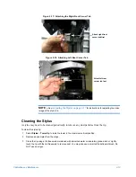
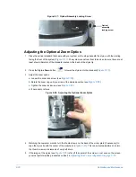
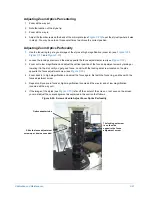
Figure 9-27: Optical Assembly Locking Screw
Adjusting the Optional Zoom Optics
1
Place the vertical standard that came with your system on the stage beneath the stylus, with the printing
facing the front of the system (
). The system scans from front to back, so be sure there are at
least a few millimeters of the standard located to the back of the stylus tip.
2
Press the
Stylus Down
button
to lower the stylus onto the standard (
3
Adjust the zoom optics:
a.
Loosen the zoom lock screw (see
b.
Rotate the zoom ring until you arrive at the desired position (see
c.
Tighten the zoom lock screw (see
).
d.
If necessary, refocus.
Figure 9-28: Adjusting the Optional Zoom Optics
4
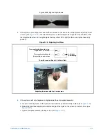
Watching the computer monitor, turn the thumb screws on the back of the mirror plate (if necessary) to
align the stylus tip with the center of the crosshairs (
). This is a delicate adjustment, so turn
the thumb screws in increments of only half a turn.
5
If the image of the stylus (see
) is far off the center of the screen, or not even on the screen,
you must performed the procedures outlined in
Adjusting the Coarse Alignment on page 9-22
Optical
assembly
locking screw
Summary of Contents for Dektak 150
Page 1: ......
Page 7: ......
Page 17: ......
Page 81: ......
Page 105: ......
Page 149: ......
Page 191: ......
Page 251: ......
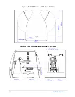
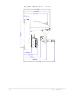
Page 257: ...A 6 Facilities Specifications Figure A 6 Dektak 150 without Enclosure Side View ...
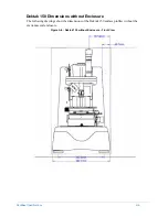
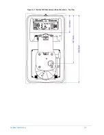
Page 258: ...Facilities Specifications A 7 Figure A 7 Dektak 150 Dimensions without Enclosure Top View ...
Page 259: ...A 8 Facilities Specifications Figure A 8 Dektak 150 without Enclosure Center of Mass ...
Page 273: ......
Page 283: ......
Page 321: ......
Page 331: ......
Page 333: ......
Page 336: ......
Page 337: ......
Page 349: ......


