2-20
Installing the Dektak 150 System
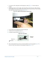
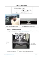
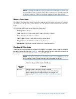
Figure 2-27: Attaching the Right-Front Corner Tab
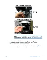
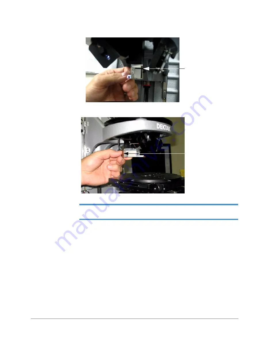
Figure 2-28: Attaching Left-Rear Corner Tab
NOTE –
As you use your Dektak 150 system, you may want to remove a stylus and install
one of a different size. For more information, see
General Care and Handling on page 9-6
.
Turning on the Power and Checking Out the System
1
Verify that the power switches on the monitor and profiler EMO box are in the On position.
2
Make sure that the switch on the surge protector is turned on.
3
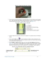
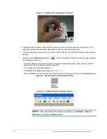
The EMO box contains three switches: a white On switch, a black Off switch, and a red Emergency Off
switch. Release the Emergency Off switch by rotating it clockwise until it pops up (see
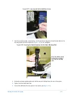
Attach right-front
corner tab first
Attach left-rear
corner tab last
Summary of Contents for Dektak 150
Page 1: ......
Page 7: ......
Page 17: ......
Page 81: ......
Page 105: ......
Page 149: ......
Page 191: ......
Page 251: ......
Page 257: ...A 6 Facilities Specifications Figure A 6 Dektak 150 without Enclosure Side View ...
Page 258: ...Facilities Specifications A 7 Figure A 7 Dektak 150 Dimensions without Enclosure Top View ...
Page 259: ...A 8 Facilities Specifications Figure A 8 Dektak 150 without Enclosure Center of Mass ...
Page 273: ......
Page 283: ......
Page 321: ......
Page 331: ......
Page 333: ......
Page 336: ......
Page 337: ......
Page 349: ......

