8
Chapter 4: Controls
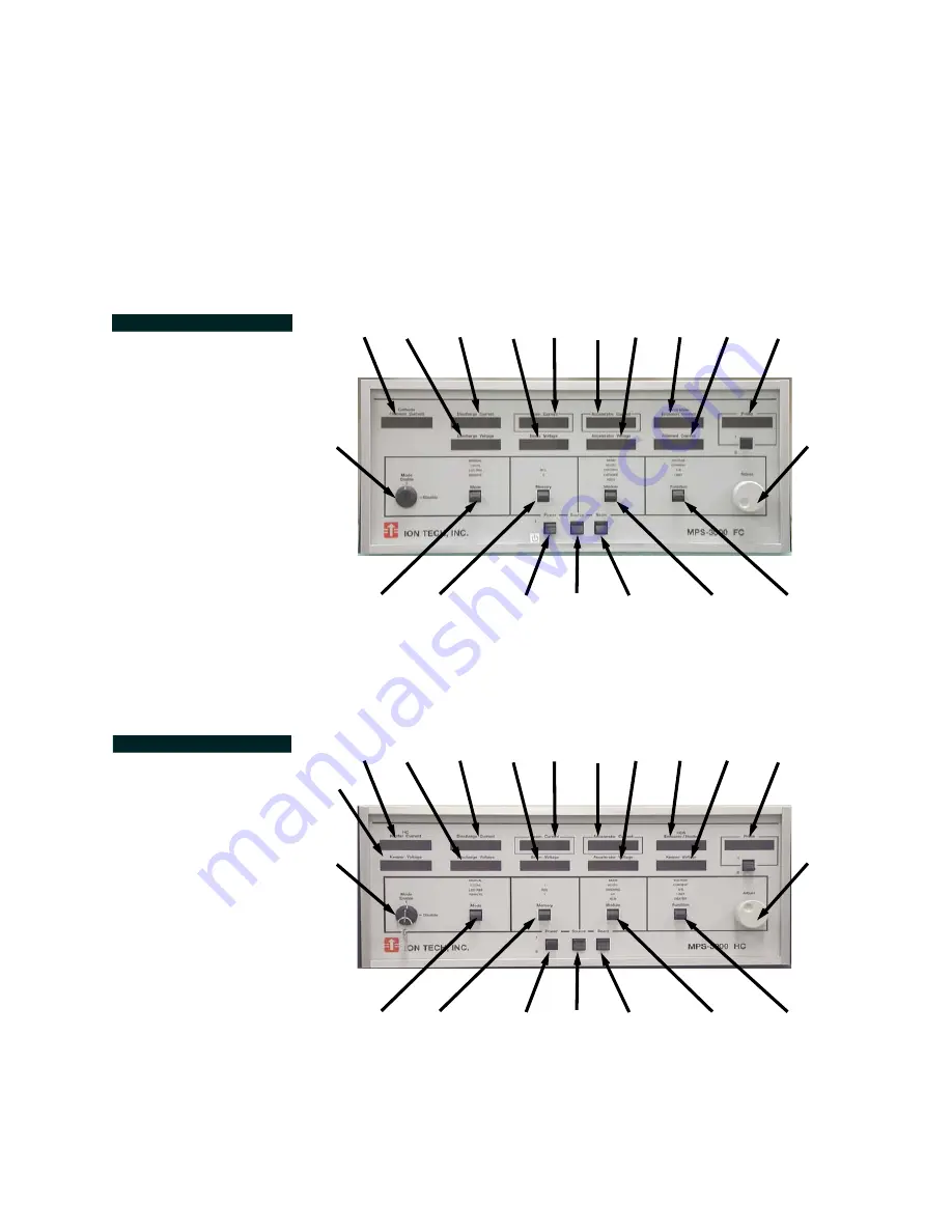
The numbers in FIGURE 4.1 through FIGURE 4.3 will appear throughout to
identify the power supply’s controls as their use and function is referenced.
FIGURE 4.1 Front
Panel: MPS-3000 CE FC
1
2
3
4
5
6
9
7
10
8
14
13
15 16
17
18
19
12
11
FIGURE 4.2 Front
Panel: MPS-3000 CE HC
1
2
3
4
5
6
9
7
8
20
14
13
15 16
22
23
19
12
11
21
Summary of Contents for MPS-3000 CE
Page 1: ...MPS 3000 CE Power Supply Technical Manual 425964...
Page 2: ...MPS 3000 CE Power Supply Technical Manual...
Page 90: ...86 Filament Cathode with Filament Neutralizer or PBN Option...
Page 91: ...87 Hollow Cathode and HCN 7 pin or 2 x 4 pin feedthrough...
Page 92: ...88 Hollow Cathode and Hollow Cathode Neut 6 pin feedthrough...
Page 93: ...89 Filament Cathode with Filament Neutralizer or PBN Option...
Page 94: ...90 3cm Source Filament Cathode and Filament Neutralizer...
Page 95: ...91 3cm Source Hollow Cathode and Hollow Cathode Neutralizer...


