IQ Control Box Installation and Owner’s Manual
Determine the Motor Type
10
Determine the Motor Type
Warning! Disconnect, lock out, an tag power to the IQ Control Box at the panel
before starting these steps.
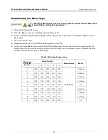
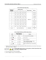
Determination of the Motor Type can be accomplished by measuring the resistance readings at the junction box in
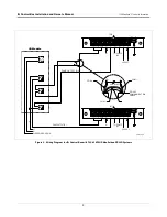
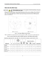
the STP and comparing to Table 1 or Table 2 below. Motor Type can also be determined by observing the flow
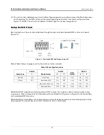
paths in the top of the UMP (Figure 10). UMPs containing a Faradyne motor will also have an ‘FM’ designation
printed on the UMP shell.
Figure 10. Identifying UMP Models By Their End View
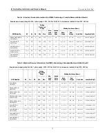
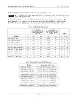
Table 1 and Table 2 show pump electrical service requirements for UMPs with end views A and B, respectively.
Table 1. Electrical Service Information (for UMPs Containing a Franklin Motor with End View A)
Required power supply rating for 60 Hz, 1 phase pumps is 208 - 230 Vac. For 50 Hz, 1 phase pumps, required rating is 220 - 240 Vac.
UMP Model No.
HP
Hz
PH
Voltage
Fluctuation
Range
Max.
Load
Amps
Locked
Rotor
Amps
Winding Resistance (Ohms)
Capacitor Kit (µF)
Min.
Max.
Black-
Orange
Red-
Orange
Black-Red
AGUMP33S1,
UMP33U1
1/3
60
1
200
250
4.0
13
7.7 - 9.4
17.4 - 21.2
25 - 30.7
144-224-5 (17.5)
E85
AGUMP75S1,
UMP75U1
3/4
60
1
200
250
6.5
25
2.9 - 3.6
14.9 - 18.2
17.7 - 21.9
410164-001 (17.5)
E85
AGUMP150S1,
UMP150U1
1-1/2
60
1
200
250
10.5
37
2.0 - 2.5
11.6 - 14.2
13.5 - 16.8
410164-002 (25)
E85
X3AGUMP150S1,
X3UMP150U1
1/1/2
60
1
200
250
10.5
37
2.0 - 2.5
11.6 - 14.2
13.5 - 16.8
410164-002 (25)

