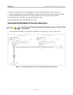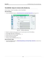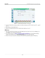
Appendix A
Upgrading IQ Control Box Software - Repeat For Each IQ Control Box
A-5
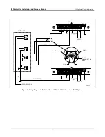
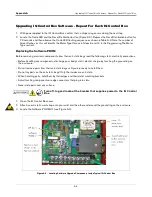
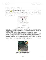
4. Position the small hooks in the ends of the chip removal tool under the ends of U1 as shown in Figure A-4.
Rock the tool lengthwise as you pull on the chip to lift it out of socket.
5. Orient the new upgrade chip with the end having a semicircle indent pointing toward TP3 as shown in
Figure A-4. Carefully align the chip pins over the holes in socket and gently push the chip into the socket.
Firmly seat the chip in the socket. Remove and discard the anti-static wrist strap.
Figure A-4. Removing Software PROM U1 From IQ Control Box
Programming the Motor Type
1.
Place the Bypass Jumper in the Bypass Position (see Figure
15).
2.
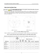
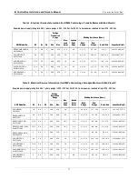
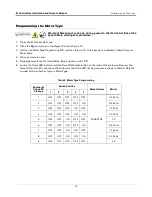
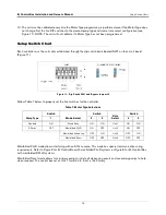
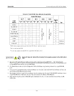
Set the five Motor Type Programming DIP switches (Figure
A-3) to the positions indicated in Table A-2 for
connected STP Motor Type.
3.
Close and secure the cover.
4.
Reapply power to the IQ Control Box. (Hook signal must be Off).
5.
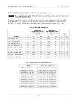
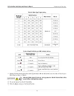
Locate the Code LED and the Reset/Calibration button (see Figure
A-3). Depress the Reset/Cal button 20
seconds and then observe the Code LED flashing sequence shown in Table A-3. Record the number of Green
flashes for your Motor Type.
6.
Release the Reset/Cal button after confirming the Green LED has flashed the correct number of times for your
selected Motor Type.

