Appendix A
Connecting RS-485 Wiring To The IQ Control Boxes
A-12
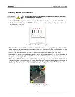
7. After the comm module(s) is installed, replace the comm module clamp and the screw that secures it.
8. Connect the IQ Control Box comm cable RJ-45 connectors to the ports of the modules installed. Record the
slot/configurable port for each cable which will be needed in the communication setup procedure.
9. Close the console’s front doors, reversing the procedure in Step 1.
10.Do not apply power to the TLS-450PLUS at this time.
Connecting RS-485 Wiring To The IQ Control Boxes
Turn off, tag and lockout the breaker that supplies power to each of the IQ
Control Boxes.
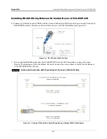
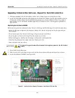
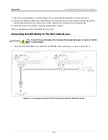
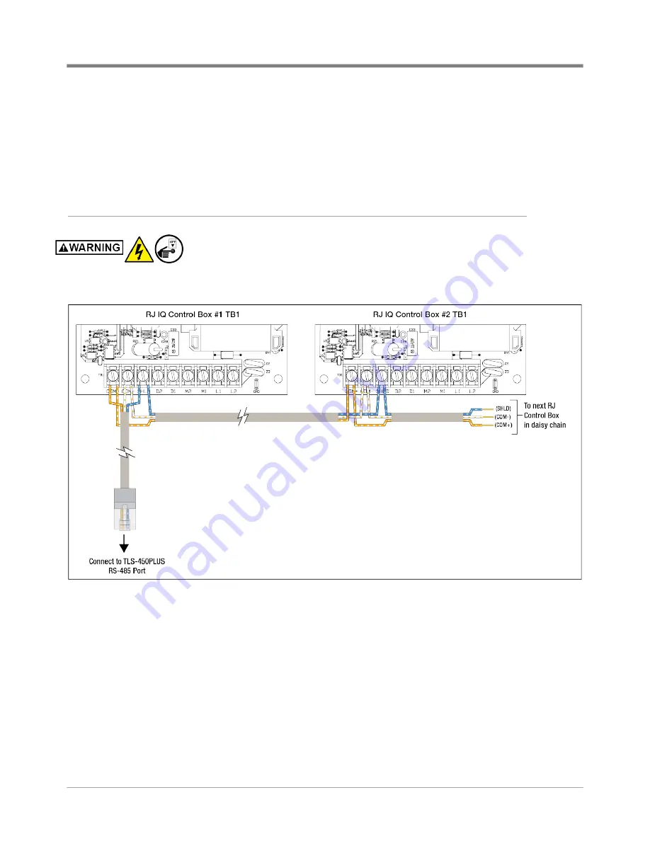
1. Open each IQ Control Box cover and attach the RS-485 comm cable wires as shown in Figure A-10.
Figure A-10. Attaching Comm Cables To RJ IQ Control Boxes (Belden 3106A Cable Shown)

