


Table of Contents
iv
Figures
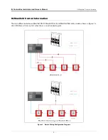
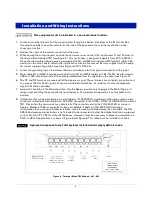
Simple Wiring Configuration Diagrams ...................................................3
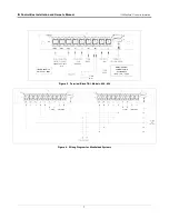
Terminal Block TB1, Models -051, -052
.................................................6
-Terminal Block TB1, Models -058, -059
................................................7
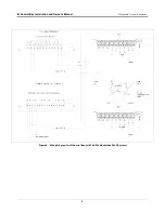
Wiring Diagram for Manifolded Systems
................................................7
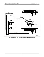
Wiring Diagram for IQ Control Box with
TLS-350 Manifolded PLLD Systems .......................................................8
Wiring Diagram for IQ Control Box with
TLS-450PLUS Manifolded DPLLD Systems ...........................................9
Identifying UMP Models By Their End View
.........................................10
Dip Switch SW1 and Bypass Jumper J3
..............................................15
RS-485 Serial Cable Pin-Outs ............................................................ A-3
Example IQ Control Box Comm Wiring Example
.............................. A-3
Locating Software Upgrade Components Inside
Typical IQ Control Box ........................................................................ A-4
Removing Software PROM U1 From IQ Control Box ......................... A-5
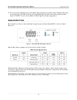
SW1 Switch Setup chart ..................................................................... A-7
Single RS-485 Port Module Jumper Positions .................................... A-9
Dual RS-485 Ports Module Jumper Positions
.................................. A-10
Comm Module Clamp Securing Screw ............................................. A-11
Comm Module Bracket Keyed Slot ................................................... A-11
Figure A-10. Attaching Comm Cables To RJ IQ Control Boxes ............................... A-12
Figure A-11. RJ IQ Comms Setup Screen
............................................................ A-13
Figure A-12. RJ Control Box Setup Screen - Unit 1 Example
............................... A-14
Figure A-13. IQ Control Box Communications Status Screen ............................... A-15
Tables
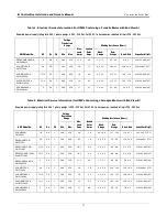
Electrical Service Information (for UMPs Containing a
Franklin Motor with End View A) .............................................................10
Electrical Service Information (for UMPs Containing a
Faradyne Motor with End View B) ...........................................................11
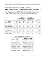
UMP Model Dimensions ..........................................................................12
Approximate Pump Shut Off Pressures ..................................................12
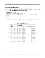
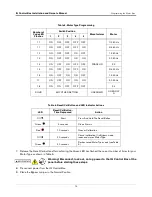
Motor Type Programming ........................................................................13
Reset/Cal Button and LED Indicator Actions ...........................................14
TLS-450PLUS Comm Module Compatibility ......................................... A-2
Motor Type Programming ...................................................................... A-6
Reset Button and LED Actions .............................................................. A-7
IQ Control Box Diagnostic Alarms ....................................................... A-15


