Appendix A
Upgrading IQ Control Box Software - Repeat For Each IQ Control Box
A-4
Upgrading IQ Control Box Software - Repeat For Each IQ Control Box
1. With power applied to the IQ Control Box, confirm that no dispensing occurs during the next step.
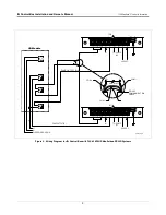
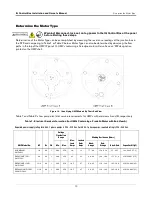
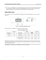
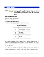
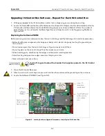
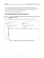
2. Locate the Code LED and the Reset/Calibration button (Figure A-3). Depress the Reset/Calibration button for
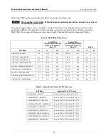
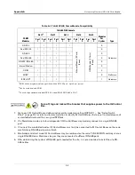
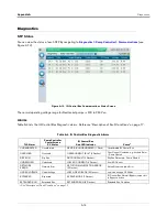
20 seconds and then observe the Code LED flashing sequence as shown in Table A-3. Note the number of
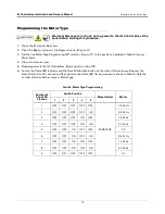
Green flashes, as this will identify the Motor Type (for use in Steps 6 and 14 in the Programming The Motor
Type section).
Replacing the Software PROM
Before removing electronic components from their anti-static bags read the following static electricity precautions.
• Before handling any components, discharge your body's static electric charge by touching the ground lug on
the enclosure.
• Do not remove parts from their anti-static bags until you are ready to install them.
• Do not lay parts on the anti-static bags! Only the insides are anti-static.
• When handling parts, hold them by their edges and their metal mounting brackets.
• Avoid touching components or edge connectors that plug into slots.
• Never slide parts over any surface.
Turn off, tag and lockout the breaker that supplies power to the IQ Control
Box.
1. Open the IQ Control Box cover.
2. Attach an anti-static wrist strap onto your wrist and the other end around the ground lug on the enclosure.
3. Locate the Software PROM U1 (see Figure A-3).
Figure A-3. Locating Software Upgrade Components Inside Typical IQ Control Box

