DPLLD Transducer Installation
Red Jacket Standard Pumps (DPLLD)
14
Red Jacket Standard Pumps (DPLLD)
Use this installation procedure to install a DPLLD transducer in a Red Jacket Standard pump that has a Functional
Element that will be used for leak detection. NOTE: This installation method is approved for 3.0 gph testing only
and cannot be used if there is a Stage II vapor recovery device installed in the pressurized piping.
Disconnect, lock out, and tag all AC power to the TLS console, dispens
-
ers and submersible pumps.
When servicing equipment, use non-sparking tools and use caution when removing or
installing equipment to avoid generating a spark.
1. If a ball valve is installed down line from the pump, close it.
2. Do
one
of the following:
a. If the submersible turbine pump is equipped with a mechanical LLD, remove the mechanical unit and any
related tubing and fittings, and install ¼” NPT pipe plugs into the respective “Line Test” and Tank Test”
ports on the packer. Be certain to apply an adequate amount of fresh, UL “Classified for Petroleum”, non-
setting thread sealant on the ¼” NPT pipe plugs and then torque each plug at 14-24 ft-lbs (19.4-29 Nm).,
or
b. If the submersible turbine pump is
not
equipped with a mechanical LLD, remove the 2-inch mechanical
LLD port plug.
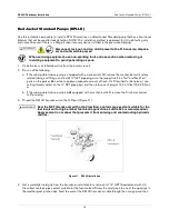
3. Thread the DPLLD transducer into the LLD port (Figure
11).
Seal the NPT threads only with a UL-Classified, nontoxic pipe sealant suitable for the
fuel involved (for high-alcohol fuel blend applications, Loctite 564 is recommended).
Apply sealant in a manner that prevents it from entering and contaminating hydraulic
cavities.
Figure 11. DPLLD Installation
4. Get a watertight cord grip from the transducer installation kit and coat its 1/2” NPT threaded end with UL-
Classified, nontoxic pipe sealant suitable for the fuel involved. Screw the cord grip into one of the openings in
the weatherproof junction box. Feed the end of the DPLLD transducer cable through the cord grip and then


