DPLLD Transducer Installation
FE Petro Pumps
19
FE PETRO HIGH CAPACITY PUMPS
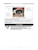
When installing PLLD in a FE Petro High Capacity pump, a FE Petro Model ‘R’ Relief Valve (P/N 401330902)
must be installed in the pump. Refer to the manufacturer’s documentation to verify that this relief valve is present. If
the ‘R’ relief valve is not present install as per manufacturer’s instructions.
You will also need to install a reducing tee (customer supplied) in the 3-inch discharge port of the pump with the 2-
inch opening facing up. Thread the PLLD transducer into the 2-inch opening of the tee.
Seal the NPT threads only with a UL-Classified, nontoxic pipe sealant suitable for the
fuel involved (for high-alcohol fuel blend applications, Loctite 564 is recommended).
Apply sealant in a manner that prevents it from entering and contaminating hydraulic
cavities.
FE PETRO VARIABLE SPEED PUMP SYSTEM MODIFICATIONS
The FE Petro variable speed pump system contains a submersible pump and adjustable frequency drive. For
satisfactory operation with the DPLLD System, you need to change the following in the adjustable frequency drive
as described below:
• Dip switch (SW2) settings
• Rotary switch positions
The correct hardware and switch settings must be used for the system to detect leaks
less than 3.0
gph. If the correct hardware and switch settings are not used, the system
will always pass 0.1 gph tests, but the passing results will be invalid.
IST-VFC Software Versions 1.1 and 1.2
The settings and positions depend on the software version of the FE Petro IST-VFC (Intelligent Submersible
Turbine-Variable Speed Controller). To determine the software version of the IST-VFC, remove its cover and check
the label on the FE Petro chip, which is on the printed circuit board. The instructions below are for Version 1.1 and
1.2 of the IST-VFC.
Dip Switch SW2
Pole 1 on dip switch SW2 (Figure
16) controls the pump start up time. Set this switch to OFF so that the
submersible pump will run at 34 psi for 6 seconds each time it is started. Pole 2 does not affect DPLLD operation;
it sets the product type for the IST
-
VFC (ref. Table 1).
.
Rotary Switch
The rotary switch (Figure
16) controls the pump pressure of the submersible pump. As shown in Table 2, use
positions 1, 2, 3, or 4 to run the pump at a pressure range compatible with DPLLD operation.
Do not use positions 0, 5, 6, 7, 8, or 9 with versions 1.1 or 1.2 software.
Table 1. FE-IST-VFC Product Type Dip Switch (SW2) Settings
Pole 1
Pole 2
OFF (required)
ON-gasoline, OFF-diesel


