23
DPLLD Wiring Connections In the Console
DPLLD Transducer Wiring Connections
• Be sure all wires are color-coded or carefully marked to identify their source and to maintain polarity.
Once a connector has been wired to a module and the console has been programmed, the
connector and module cannot be moved to another slot without reprogramming the system.
• Record the location (e.g., Line #1 (regular), Line #2 (super), etc.) of each DPLLD transducer on the circuit
directory inside the right-hand console door.
Disconnect, lock out, and tag all AC power to the TLS console, dispens
-
ers and submersible pumps.
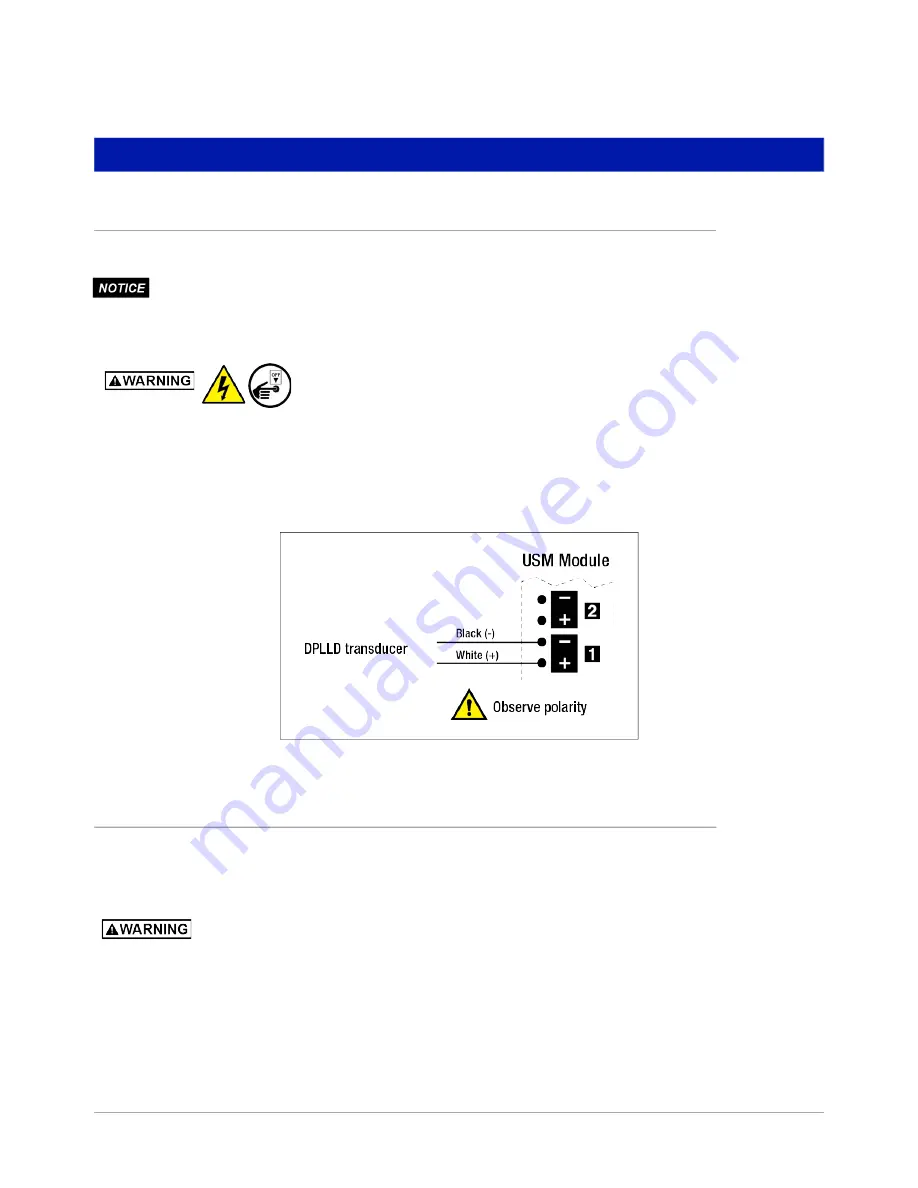
1. Connect the two color-coded or marked wires from each DPLLD transducer to the USM module. (see
19). Maintain correct polarity between the color-coded or marked field wires and the connector
terminals during wiring.
2. Connect the transducer cable’s bare wire (shield) to one of the ground lugs in the TLS console.
Figure 19. DPLLD Transducer Wiring To USM Module
Pump Wiring Connections
The console must be able to detect when dispensers are switched On or Off so it only initiates line leak tests
when the dispenser is switched Off. The console must also be able to start the submersible pump to perform a line
leak test, and shut off the pump if a leak is detected.
Dispensers and TLS console must be wired to the same leg of incoming power at the
main electrical panel; otherwise damage to both may result.
The console, when wired correctly, will control the pump independent of the dispenser
control circuits. It is imperative that when the emergency stop switch is wired and tested,
the console’s pump control circuitry CANNOT start up the pump. To ensure that the
pumps are unable to be activated in an emergency situation, have the emergency stop
switch interrupt pump power at the circuit breaker panel via shunt breakers.


