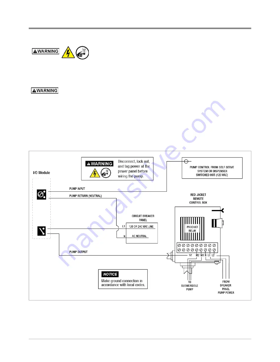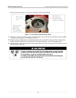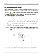
DPLLD Wiring Connections In the Console
Pump Wiring Connections
24
Disconnect, lock out, and tag all AC power to the TLS console, dispens
-
ers and submersible pumps.
1. Referring to the appropriate wiring diagrams below, pull the necessary number of #14 AWG color-coded or
marked copper wires from STP control boxes, self-serve system/dispenser, and power panel to the
appropriate I/O module of the TLS console. Since wiring for multiple pump controls may be entering the
console through the same conduit opening,
color code or mark each wire to identify its source!
The dispensers and TLS console must be wired to the same leg of incoming power at the
main electrical panel; otherwise damage may result to dispensers and console.
2. DPLLD pump control wiring varies depending on the pump manufacturer’s relay control box. Refer to the
appropriate wiring diagram example below to connect DPLLD controlled pumps to the I/O Module in the TLS
console (circuit diagrams are for switched ‘hot’ dispensers):
•
Red Jacket (ref. Figure
•
Non-Red Jacket (ref. Figure
•
Manifolded tanks (ref. Figure
27)
•
Gilbarco dispenser isolation box (ref. Figure
25)
Figure 20. DPLLD Pump Control Diagram For Red Jacket Relay Control Box


