20
EMR4 Terminal & Fueling Depot Installation
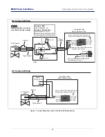
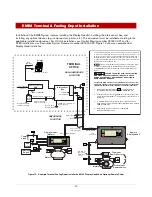
Installation of the EMR4 System involves installing the Display Head(s), installing the interconnect box, and
installing any optional devices (e.g., remote pulser, printer, etc.). This equipment must be installed according to the
applicable installation document. For UL/cUL installations use Control Drawing number 331940-021 and for
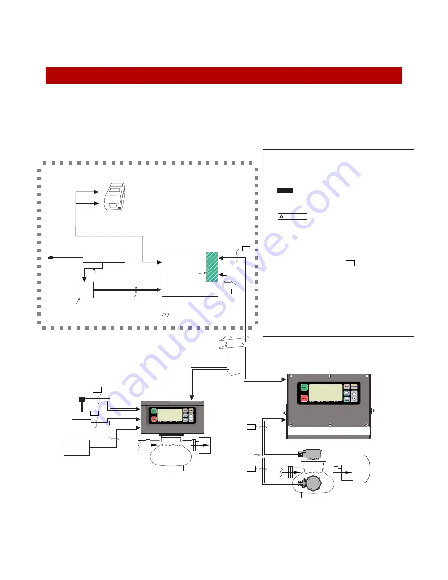
ATEX installations use Descriptive System Document number 331940-022. Figure 13 shows an example dual
Display Head installation.
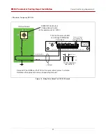
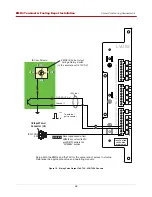
Figure 13. Example Terminal Fueling Depot Installation With 2 Display Heads And Optional Remote Pulser
TERMINAL
OFFICE
HAZARDOUS
LOCATION
NON-HAZARDOUS
LOCATION
Rigid conduit
Interconnect
Box
Printer
D
a
t
a
(R
S
-2
3
2)
D
a
t
a
(R
S
-4
8
5)
D
a
t
a
(R
S
-4
8
5)
Power
Power
Power
120 or 240Vac
line cord
Se
a
l-off
UL
a
pproved 120W
i
s
ol
a
ted
s
econd
a
ry
Inp
u
t R
a
ting: 10–2
8
Vdc, 5 A
120 or 240Vac line
12 Vdc
Power
S
upply
Cu
s
tomer
s
upplied
wiring & rigid conduit
24 Vdc
Temp
Probe
UP
S
AC Power Protector
The following inform
a
tion i
s
for gener
a
l reference
a
nd i
s
not intended
to repl
a
ce recommended n
a
tion
a
l electric code (nec) proced
u
re
s
. it i
s
import
a
nt for the in
s
t
a
ller to
u
nder
s
t
a
nd th
a
t wiring loc
a
ted in Cl
ass
I,
Gro
u
p D Divi
s
ion 1
a
nd 2 in
s
t
a
ll
a
tion
s
or Cl
ass
I, Zone 0, Gro
u
p IIA
loc
a
tion
s
s
h
a
ll comply with the l
a
te
s
t
a
ppropri
a
te
a
rticle
s
fo
u
nd in the
N
a
tion
a
l Electric Code (NFPA 70).
Thi
s
i
s
a
control dr
a
wing only
a
nd doe
s
not reflect the
a
ct
ua
l
loc
a
tion
s
of cond
u
it entry. In In
s
t
a
ll
a
tion
a
nd
us
e of thi
s
prod
u
ct,
comply with the n
a
tion
a
l electric
a
l code; Feder
a
l,
S
t
a
te
a
nd Loc
a
l
Code
s
.
FAILURE TO COMPLY WITH THE FOLLOWING
WARNING
S
AND
S
AFETY PRECAUTION
S
COULD CAU
S
E
DAMAGE TO PROPERTY, ENVIRONMENT, RE
S
ULTING IN
S
ERIOU
S
INJURY OR DEATH.
The Di
s
play Head mu
s
t never be operated unle
ss
the front cover
and wirin
g
s
hield are clo
s
ed and properly
s
ealed over the barrier
terminal
s
in the intrin
s
ically
s
afe area of the Interconnect Box.
1. Intrin
s
ic
a
lly
sa
fe wiring (m
a
rked )
s
h
a
ll
b
e in
s
t
a
lled in
a
ccord
a
nce with Article 504 of the NEC, AN
S
I/NFPA 70.
2. In the non-intrin
s
ic
a
lly
sa
fe comp
a
rtment of the Interconnect Box,
connect the #12 AWG (4mm
2
) or l
a
rger di
a
meter
ba
rrier wire to
a
gro
u
nd l
u
g.
3
. To
m
a
int
a
in intrin
s
ic
sa
fety, di
s
pl
a
y he
a
d to interconnect
b
ox
wiring m
us
t
b
e r
u
n in dedic
a
ted cond
u
it. M
a
xim
u
m c
ab
le length i
s
1,000 feet (
3
04.
8
M).
4. Di
s
pl
a
y He
a
d m
us
t
b
e connected to e
a
rth gro
u
nd
thro
u
gh it
s
mo
u
nting
s
crew
s
.
Di
s
play Head 1
(Meter 1)
EPSON TM-U220A ROLL
Meter 2
Remote
Di
s
play Head 2
Top mount
Remote Pul
s
er
Front mount
Remote Pul
s
er
5 Vdc
P
u
l
s
e Inp
u
t
M
a
x. Remote
Pul
s
er c
ab
le
length 35 ft.
(10.6 m)
Meter 1
OR
M
a
x. c
ab
le length
1000 ft. (304.8 m)
I.S.
I.S.
I.S.
I.S.
I.S.
I.S.
I.S.
Connected to
E
a
rth Gro
u
nd
12 AWG U.
S
. (4mm2 E.U.)
B
a
rrier Gro
u
nd
WARNING
NOTICE
Intrin
s
ic
S
a
fety B
a
rrier
Interlock
S
witch
I.S.
E
SS
S
witch


