21
EMR
3
- Truck Installations
EMR4 Terminal & Fueling Depot Installation
Wiring The Display Head
Wiring The Display Head
1.
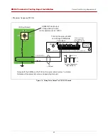
With the Display Head cover still off, remove the nut and bushing from the right side panel cord grip
connector. Note: the maximum cable length between the Interconnect Box and the Display Head is 1000 feet
(304.8 meters).
2.
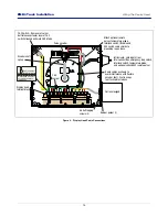
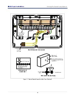
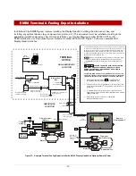
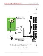
Slide the cord grip nut and then the bushing over the IB cable leads. Pull enough cable through so that the
leads reach the terminal block on the display assembly and can be tie wrapped to the pulse encoder mounting
base as shown in Figure 14. Slide the tapered end of the bushing into the cord grip, then screw on the cord
grip nut and tighten securely.
3.
Attach the four-wire IB cable to the terminal block as shown in Figure 14.
When stripping wire for terminal block connections, be careful not to nick the individual strands. Also, be sure
to tighten each terminal so the wire can not be pulled out. A failure to follow either of these instructions can re-
sult in signal loss and faulty operation.
4.
If you have the optional temperature probe and/or ESS switch, remove the lower cord grip nut and slide it,
then the tapered bushing, over the temperature probe cable and/or ESS switch cable. Pull enough cable
through so that the leads reach the terminal block on the display assembly and can be tie wrapped to the
pulse encoder mounting base as shown in Figure 14. Slide the bushing into the cord grip and then screw the
cord grip nut onto the cord grip and tighten securely. Attach the shield of the temperature probe cable to a
grounding lug on the Pulse Encoder mounting base.
5.
Attach each wire (no polarity) of the 2-connector temperature probe cable and/or ESS switch where shown
on the terminal block label.
6.
Tie wrap the IB, ESS switch and temp probe (if installed) cables to the pulse encoder mounting base.
7.
For transfer Interlock applications, attach the two wires in the switch cable where shown on the terminal block
label and tie wrap the cable to the pulse encoder’s mounting base.
8.
Replace the Display Head cover and screw in the four cover retaining bolts just enough to hold them in (the
cover will be removed later for system calibration).


