30
EMR4 System Specifications
System Power
10 - 28 Vdc, fused @ 5 A.
Component Location
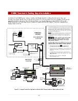
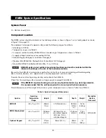
The EMR4 system should be located on a fuel delivery vehicle as shown in Figure 1 or in a fueling depot as shown
in Figure 13 on page 20.
The equipment is designed to operate safely under the following range of conditions:
• Altitude up to 2000m.
• Temperature range - see Table 3.
• A maximum relative humidity of 95% RH (non-condensing) at temperatures shown in Table 3.
• A supply voltage fluctuation not exceeding 28 Vdc.
• Pollution Degree Category 2, Installation Category II.
• Vibration: MIL-STD-810G, Method 514.6; Table 514.6 C-VI Category 4
• Shock: MIL-STD-810G, Method 516.6; 20G, 11ms, 1/2-Sine
EMR4 IB units are not suitable for external locations and must be installed within the
interior of buildings or the cab of the fuel deliver vehicle.
Ensure that the
EMR4 IB
is located where neither the unit itself nor its associated cabling will be damaged by
doors, furniture, barrows, etc. - depot installs or nearby equipment - vehicle installs.
Consider the ease of routing wiring, ducting and cables to the
EMR4 IB
.
Check that the mounting surface material is strong enough to support the
EMR4 IB
.
If the EMR4 IB requires cleaning, do not use any liquid materials (e.g. cleaning solvents).
It is recommended that the unit be wiped with a clean dry cloth when necessary.
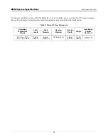
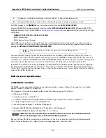
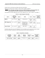
Overall dimensions and the weight of the various system components are as shown in Table 3 and Table 4:
Table
3
. System Component Dimensions
System
Operating
Temperature
Range
Height
Width
Depth
Weight
Descriptive
System
Document
EMR4 IB
-25°< Ta < 40°C
254mm
(10 in.)
215.9mm (8.5 in.)
80.9mm
(3.185
in.)
7.6 lbs
(3430 g)
331940-022
EMR4 Display Head
-40°< Ta < 60°C
129.6mm
(5.1 in.)
241.3mm (9.5 in.) -
w/o optional keypad
330.2mm (13 in.) -
w/optional keypad
215.9mm
(8.5 in.)
11 lbs
(4990 g)
Optional Keypad
-40°< Ta < 60°C
117mm
(4.6 in.)
92mm (3.6 in.)
59mm
(2.3 in.)
1 lb
(454 g)
NOTICE
NOTICE

