4
EMR
3
- Truck Installations
EMR4 Truck Installation
Installing The Interconnection Box (IB)
Installing The Interconnection Box (IB)
The IB box is not rated for mounting in outdoor locations. The IB box can be mounted only
in a protected enclosure or protected location.
The following information is for general reference and is not intended to replace recommended National Electric
Code (NEC) procedures. It is important for the installer to understand that electrical equipment and wiring located
in Class I, Division 1 and 2 installations shall comply with the latest appropriate articles found in the National
Electric Code (NFPA 70) and other applicable code requirements.
1.
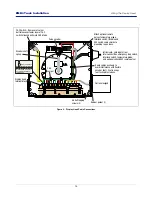
The physical dimensions of the Interconnection Box (IB) are shown in Figure 2.The IB is installed in the truck’s
cab either under the seat, mounted on the wall inside the cab, mounted to the passenger side of the “dog
house” in cab-over trucks, or mounted to a custom-made bracket that can also support the optional printer.
Use four, 3/16” (4 mm) bolts to mount the IB to the mounting surface. In the event of limited access, the front
cover of the IB can be completely removed rather than swung open, by removing four #15 Torx screws. Put
the excess coils of cable under the seat or clamp them to the IB mounting stand.
2.
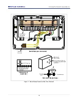
Figure 3 shows IB Power Side terminal wiring connections. Remove hole plugs and use cord grips for all
cables attaching to this terminal block.
Run the power cable from the truck fuse block or ignition switch to the IB. Clamp the power wire at suitable in-
tervals between the power source and the IB.
Before connecting the truck power wiring, verify the following:
a. Electrical system has a negative ground.
b. Battery terminals and cables are in good condition.
c. Alternator current output is sufficient to supply EMR4 System current requirement of 5 amperes.
3.
Attach the wire from truck ground to the GND terminal of the Power Side terminal block (J8, Pin 2). Also
attach the wire from the truck’s Accessory (ACC) circuit to the Input-Pwr terminal of the terminal block (J8-Pin
1).
4.
Refer to Figure 3 for the IB intrinsically safe terminal wiring connections. Remove hole plugs and use cord
grips for Display Head cable entries. The drain wire from the Display Head cable must be connected to the
chassis ground clamp in the Interconnect Box.
Input Power – Critical Ground Connection
On some vehicles, the battery minus terminal, BAT(-), may not be common with the chassis ground or the defined
vehicle ground located in either the accessory panel or in the power distribution box. In this case, directly run the
ground connection for Input Power at J8, Pin 2 (GND) terminal as shown in Figure 3, directly to the BAT(-) terminal
connection point.
Proper operation of the EMR4 hardware depends on the quality of the ground connection from the Interconnect
Box to the source of INPUT-PWR power.
If the INPUT-PWR connection is made at the accessory panel, it must be fused at 5 amps. The installer must
ensure that a minimum of 12.0 volts, between the INPUT-PWR terminal and the GND terminal, is available from
the power source. If an improper ground point is used for input power to the EMR4 there may be insufficient
power for the Display Head to operate properly resulting in various E## error codes or possibly a blank display.
Pay careful attention to the wiring labels on both the EMR4 Display Head and the Interconnect Box.
Each connection must be made according to the wiring tables listed in this manual. Use shielded
cable to connect each device to the Interconnect Box and Display Head and ensure that each cable
jacket is resistant to gas and oil.
NOTICE


