3
I N S T A L L A T I O N
WIRING
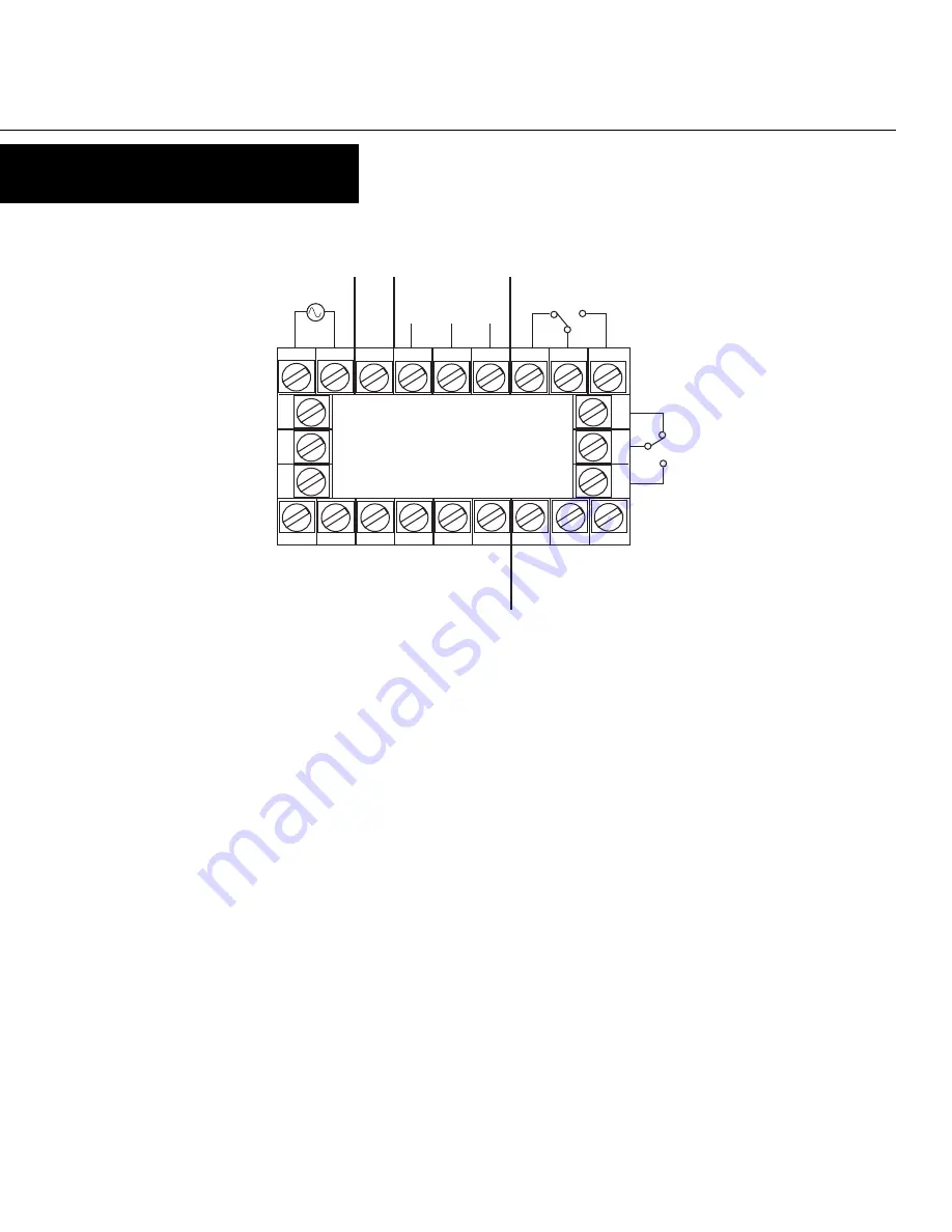
REAR TERMINAL CONNECTIONS
Count Inputs
Terminal #2 is the connection for Input A, which is programmable to be
the primary input or channel A of an encoder input. Terminal #1 is the
connection for Input B, which is programmable to be an incrementing
input, a decrementing input, or channel B of an encoder input. The
common connection for both Input A and Input B is Terminal #3.
Control/Digital Inputs
A contact closure or NPN signal can be used to activate preconfigured
functionality. Terminal # 5 is used for a remote reset function, while
Terminal #6 is a security function, that when active, will prohibit entry
into Program Mode. Terminal #8 serves as the common for both of these
inputs.
Auxiliary Power Output
A 9 - 15 VDC for powering external sensors and encoders up to 125 mA
can be accessed by connecting the positive supply side of the sensor to
Terminal #4 and the negative side to Terminal #8.
Input Power
For an AC powered unit, Terminal #13 serves as the line or Hot side
connection for AC powered units and as the positive side for DC powered
Terminals 10, 11, 12, & 15 are not used.
units. The neutral side for AC powered units and the negative side for
DC powered units are connected to Terminal #14.
Transistor Outputs
Your unit comes standard with 2 NPN outputs which are activated by
each of the presets. Transistor Output 1, which is tied to Preset 1
operation, is on Terminal #7. Transistor Output 2, which is tied to Batch
Preset operation, is on Terminal #9. Terminal #8 serves as the common
connection for both transistor outputs.
Relay Outputs
Your unit comes standard with a relay output which is tied to Preset 1
operation. Terminal #19 is NC, Terminal #20 is common, and Terminal
#21 is NO. A second relay output tied to the operation of Batch Preset
can be added as an option at the time of order or later installed in the
field. Terminal #22 is NC, Terminal #23 is common, and Terminal #24 is
NO.
Serial Communication
An RS-485 communication board, utilizing ASCII protocol, can be
installed as an option. Terminals #16 & #17 serve as the B and A
connections respectively, while Terminal #18 is connected as the
common.
2
3
4
5
6
7
8
24
23
22
14 15 16 17 18 19 20
10
1
1
12
B A
COM
Power Supply
+ VDC -
RS-485 Comm.
(opt.)
Input B
Input A
Input Common
Aux. Power
(opt.)
Digital In 1 (rem. reset)
Digital In 2
(sec. lockout)
Common
Relay 2
(opt.)
Relay 1
NPN Out 1
NPN Out 2


