Console Installation
Mounting the Console
12
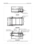
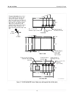
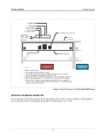
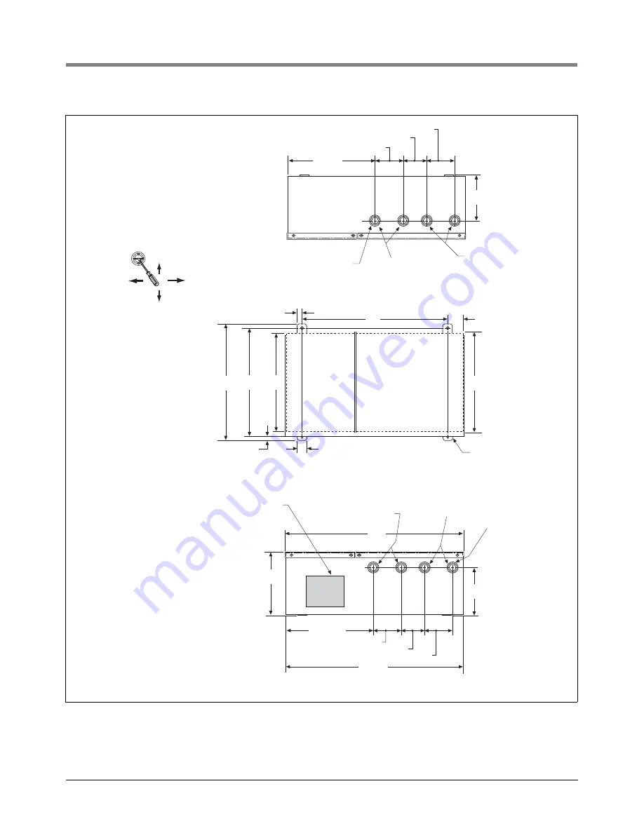
Figure 6. TLS-350/ProMax/EMC Console Dimensions and Designated Conduit Knockouts
16''
1-7/8''
11-1/4''
11''
13''
1/2'' TYP.
1'' TYP.
12''
FRONT VIEW
20''
7-3/16''
5-3/32''
2-9/16''
3-1/8''
9-11/16''
19-3/4''
BOTTOM VIEW
consoles\350cndim.eps
Mounting flanges
w/ 1/4'' x 3/8''
slotted hole
(typ. 4 places)
3-1/8''
1/2'' TYP.
5-3/32''
2-1/2''
3-1/8''
3-1/8''
9-3/4''
TOP VIEW
3/4, 1, 1-1/4 I.P.S.
knockouts
(typ. 4 places)
3/4, 1, 1-1/4 I.P.S.
knockouts (typ. 4 places)
To remove a knockout,
insert a flat
head screwdriver into the slot in the
center of the knockout and gently
move the screwdriver up and down to
remove the inner knockout, or left and
right to remove the middle knockout.
Keep up this movement until the
connecting tabs break off. To remove
the outer or largest knockout, use
pliers to break out the remaining large
ring.
Inner
knockout
Middle
knockout
Access to communication
modules and end plate
connectors
Conduit entries to
power bay
Conduit entries to
power bay
Conduit entries to
intrinsically-safe bay
Conduit entries to
intrinsically-safe bay

