26
Mag Probe Installation
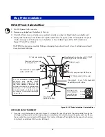
UST/AST Tank - Dedicated Riser
1.
Turn OFF power to the console.
2. Remove any sludge from the bottom of the tank.
3. Check that floats, boot, and cable are assembled correctly on probe (ref. Mag Probe Assembly Manual).
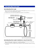
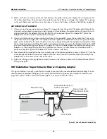
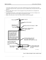
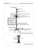
4. Gently slide the float(s) to the bottom of the probe shaft before raising the probe. Carefully lower the probe
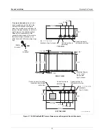
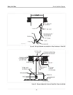
into the riser pipe until the boot rests on the bottom of the tank [See Figure 20 for UST installation or
Figure 21 for AST installation].
CAUTION! Handle probes carefully. Striking or dropping the probe will result in loss of calibration and could
cause permanent damage.
Figure 20. UST Probe Installation - Dedicated Riser
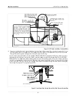
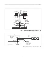
UST RISER CAP ATTACHMENT
1.
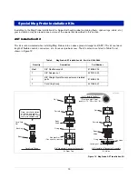
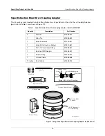
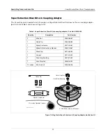
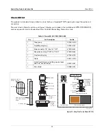
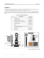
If you are using the one piece cap (see Figure 17 on page 24), push the end of the probe cable through the
cord grip bushing and nut on the cap, leaving a minimal amount of slack between the probe and cap. Screw
the cap onto the riser by hand until the gasket first contacts the pipe. Then lightly tap the cap with a hammer
to tighten it an additional 3/4 turn. Go to Step 3.
OFF
.
.
.
.
.
.
.
.
.
.
.
.
.
.
.
.
.
.
.
.
.
.
.
.
.
.
.
.
Riser cap with cord grip
bushing and nut
Concrete slab or packed
earth per NFPA 80
Riser pipe: 2-, 3-, or 4'' API schedule 40
depending on probe type
Cord grip seals
Weatherproof junction box with 1/2" NPT
threads (16 cubic inch minimum)
14'' min. dia. manhole
Seal-off, epoxy seal per NFPA spec
Mag Probe
(rests on bottom)
Tank
A = 10" minimum for global mag
plus/mag plus probes. When
installing a probe longer than the
the tank diameter,
increase this
minimum dimension to compensate.
(Example: a 7'-6'' diameter tank will
use an 8' probe, in which case you
must add 6" to minimum riser length
'A', i.e., 16").
probes\pbinstcen.eps
1/2" Rigid conduit (to Console)
Probe cable
A
Split-Ring Collar
(P/N 576008-617)
required if probe
enters the riser.
Top view
Side view
3/4" ID

