Sensor Installation
Sensor Installation Diagrams
43
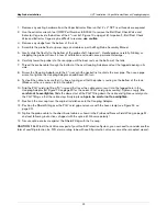
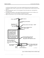
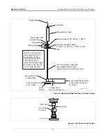
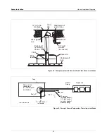
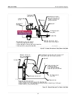
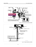
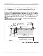
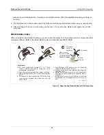
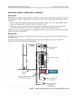
Figure 39. Example Dispenser Pan Sensor Installation in a Containment Sump
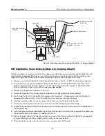
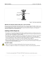
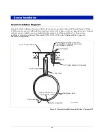
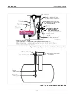
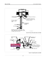
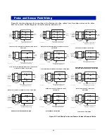
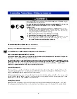
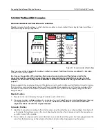
Figure 40. Typical Oil/Water Separator Sensor Installation
sensors\dispscin.eps
Rubber grommet seal
clamped on inside -
or as recommended by
dispenser pan manufacturer.
Weatherproof junction box with
1/2-inch N.P.T. threads (16 cubic
inch volume minimum).
1/2'' Rigid conduit
to console
Seal-off
Cord grip
Brackets, clamp, etc., from
Universal sensor mounting kit
*Dispenser pan sensor should:
1. Rest in the cup or the lowest point of the dispenser containment sump.
2. Be positioned so as to be removable by pulling the sensor straight up out of the pan.
3. Be mounted in a true vertical position.
Dispenser pan sensor*
Dispenser
containment
sump
U-channel
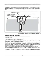
Product line
IMPORTANT!
DO NOT MOUNT SENSOR TO
FLEXIBLE PRODUCT LINE.
IMPORTANT!
DO NOT MOUNT SENSOR TO
FLEXIBLE PRODUCT LINE.
Top of level sensor riser
sensor\ow2_snsr.eps
2"NPT threaded opening
3.5" min clearance above riser top
for sensor clearance
Top float
switching point
Bottom float
switching point


