background image

Connecting Probe/Sensor Wiring to Consoles

TLS-

3

50/ProMax/EMC Consoles

69

I/O COMBINATION MODULE - POWER BAY

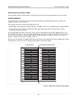
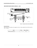
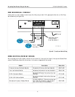
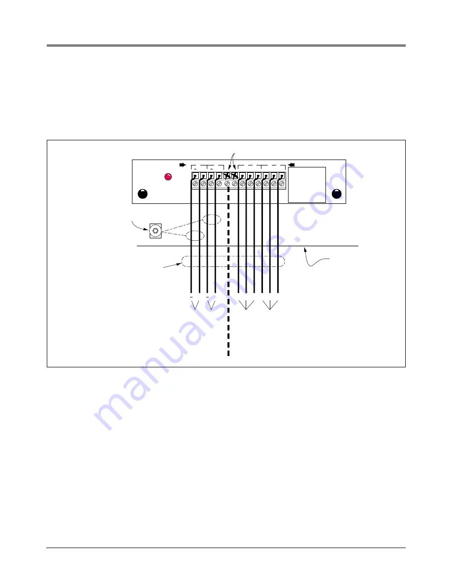
The I/O Combination Module can accept two dry-contact switch closure inputs from an external device such as a 
line leak detector or well monitoring system [Figure 67].]

For each external input, connect a shielded cable consisting of two #18 AWG conductors to the appropriate input 
terminals on the module.

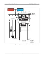
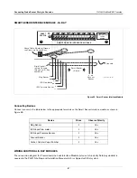
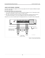
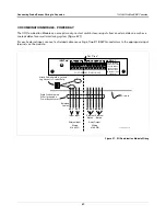
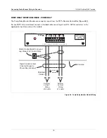
Figure 67.  I/O Combination Module Wiring

INPUT

I/O COMBINATION MODULE

RELAY

consoles\iocmw.eps

Console

Attach Cable Shield to Ground 
Lug Closest to Conduit Entry

+

+

Input

Input

Shielded 

Cables

External Input 

Wiring

#18 AWG

NC NO C

External

Device

Relay Output 

Wiring

#14 AWG

NC NO C

External

Device

Not Used

Rigid Conduit (enters 
Console through a 
Power Bay knockout)

+

+

1

2

3

NC NO C

3

NC NO C

4

4

RELAY RATINGS

FORM C CONTACTS

120 VAC 2A MAX

24 VDC 2A MAX
FUSE RATINGS

2A 250VAC TYPE T

(SLO-BLO)

Summary of Contents for TLS-3 Series

Page 1: ...Manual No 576013 879 Revision W Site Prep and Installation Manual Veeder Root TLS 3XX Consoles ProPlus ProMax Series Consoles Gilbarco EMC Series Consoles...

Page 2: ...and Conditions VEEDER ROOT S PREFERRED CARRIER 1 Contact Veeder Root Customer Service at 800 873 3313 with the specific part numbers and quantities that were missing or received damaged 2 Fax signed...

Page 3: ...g Mag Probe Riser Size Probe Riser Pipe Installation 16 Determining Mag Probe Length Determining Mag Probe Length 17 Determining Mag Probe Length for Installation in a Vapor Extractor Riser 17 Determi...

Page 4: ...ensor Wiring to Consoles TLS 300 ProPlus EMC Basic Consoles 54 Probe and Sensor Wiring Precautions 54 Circuit Directory 54 Connecting Probes and Sensors to the Console 55 Connecting Devices to Power A...

Page 5: ...aptor Installation Kit 20 Figure 14 Mag Probe Vapor Extractor w o Coupling Adaptor Installation Kit 21 Figure 15 Mag Plus Probe Chem ISO Kit 22 Figure 16 Mag Plus Probe LPG ISO Kit 23 Figure 17 Cap an...

Page 6: ...ole System Circuit Directory 59 Figure 58 Probe Thermistor Interface Module Wiring 60 Figure 59 3 Probe 3 Sensor Interface Module Wiring 61 Figure 60 Interstitial Sensor Interface Module Wiring 62 Fig...

Page 7: ...ntractors holding valid Installer Certification are approved to perform wiring and conduit routing equipment mounting probe sensor and carbon canister vapor polisher installation wireless equipment in...

Page 8: ...576013 623 TLS 3XX System Setup Manual 576013 858 Direct Burial Cable Installation Manual 577013 744 Mag Plus Probe Installation Guide 577013 528 Serial Comm Modules Installation Instructions for Modu...

Page 9: ...material suitable for the environment such as Carol C2534 or Belden 88760 8760 8770 or similar Note Throughout this manual when mentioning any cable or wire being used for probe and sensor to console...

Page 10: ...00 pF foot Inductance does not exceed 0 2 H foot POWER WIRING Wires carrying 120 or 240 Vac from the power panel to the console should be 14 AWG or larger copper wire for line neutral and chassis grou...

Page 11: ...THIS COVER MUST NOT BE REMOVED MAXIMUM PROBE OUTPUT RATINGS 13 VDC 20 AMP 1 2 3 4 PROBE MAXIMUM SENSOR OUTPUT RATINGS 13 VDC 20 AMP 5 6 SENSOR 7 8 1 2 3 4 consoles 30 003 eps Optional printer Conduit...

Page 12: ...e console s Comm modules attach to connectors on each module s end plate and are accessible through an opening in the base of the console Note that the number type of modules in your console may diffe...

Page 13: ...its but the intrinsically safe sensor and probe wiring can NOT share the same conduit with any other wiring Also the intrinsically safe wiring for console can NOT share the same conduit with another d...

Page 14: ...Connection IS IS PA IS Conduit Enters Console in an Intrinsically Safe Area Knockout Conduit Enters Console in a Power Area Knockout IS PA TLS 300 ProPlus EMC Basic Product piping Double Wall Tank Si...

Page 15: ...nstalled in accordance with Article 504 20 of the latest National Electrical Code NFPA 70 See Control Drawing 331940 011 for Intrinsically Safe Wiring WARNING Substitution of components may impair int...

Page 16: ...ted to the console Mounting the Console Install the console fastening devices to the mounting surface using the hole pattern shown in Figure 5 or Figure 6 Up to 1 4 diameter screws may be used Mount t...

Page 17: ...16 3 9 16 19 3 4 13 1 16 2 1 2 16 1 7 8 11 1 4 11 13 1 2 TYP 1 TYP 12 1 2 TYP Conduit Entries To Intrinsically Safe Area 3 4 1 I P S Knockouts Typ 4 Places Conduit Entry To Power Area 1 2 3 4 I P S Kn...

Page 18: ...S knockouts typ 4 places To remove a knockout insert a flat head screwdriver into the slot in the center of the knockout and gently move the screwdriver up and down to remove the inner knockout or le...

Page 19: ...hock that may result in serious injury or death Routing conduit for power wires into the intrinsically safe compartment can result in fire or explosion resulting in serious injury or death OFF L G N A...

Page 20: ...BAY INTRINSICALLY SAFE BAY consoles pwrmwir eps F U S E F USE 2A Slo Blo 5 mm x 20 mm POWER MODULE POWER WIRING NOTES 1 Barrier ground must be 12 AWG or larger 2 Check to be sure that the electrical...

Page 21: ...o not run probe and sensor wiring to separate consoles in the same conduit Do not run probe and sensor wiring with other equipment s intrinsically safe wiring in the same conduit Improper system opera...

Page 22: ...imum riser dimensions for use with Veeder Root mag probe float sizes DN Diameter Nominal NPS Nominal pipe size Pipe type is iron or schedule 40 steel Table 1 Dimensions for Steel Riser Pipes and Mag P...

Page 23: ...ractor Riser 1 Measure the distance from the top of the riser to the Extractor Cage Cross Pin see Figure 10 Record this distance as D1 Important Dimension D1 must be at least 25 inches 2 Use the extra...

Page 24: ...h for Media Isolated Installations If tank s inside diameter is unknown perform the following procedure ref Figure 11 1 Measure the distance from the inside bottom of the tank to the inside top of the...

Page 25: ...Mag Probe AST Installation Kit Table 2 Mag Probe AST installation kit Part No 312020 984 Quantity Description Part Number 5 feet 3 8 Flexible conduit 576008 294 1 3 8 Adaptor nut 329972 002 2 3 8 Str...

Page 26: ...No 846500 001 Quantity Description Part Number 2 Wire Nut 576008 461 1 Cable Tie 576008 482 1 Splice Enclosure 514100 357 1 Splice Kit Instructions Manual 576013 861 1 PG7 1 4 Cord Grip Fitting 576008...

Page 27: ...Coupling Adaptor Installation Kit Table 4 Vapor Extraction Riser Kit w o coupling adaptor Part No 846500 002 Quantity Description Part Number 2 Wire Nut 576008 461 1 Cable Tie 576008 482 1 Splice Encl...

Page 28: ...3 001 1 Male connector 7 8 tube to 1 NPT 576008 643 1 Reduction bushing 2 NPT to 1 NPT 576008 645 1 Float retaining ring 511805 378 1 Cable 330272 XXX 1 Cable Seal Kit cord grip fitting sealant pack w...

Page 29: ...XXX 1 Float Magnet group 331797 001 1 Male connector 7 8 tube to 1 NPT 576008 643 1 Reduction bushing 1 1 2 NPT to 1 NPT 576008 644 1 Float retaining ring 511805 378 1 Cable 330272 XXX 1 Cable Seal Ki...

Page 30: ...his Riser Cap kit Table 7 contains a non metallic cap which screws onto the 4 NPT riser Figure 17 The cap comes drilled and tapped with a cord grip Figure 17 Cap and Cord Grip Kit METAL CAP AND RING K...

Page 31: ...028 001 as follows 1 Remove the cap to a non hazardous location 2 Drill and tap the cap for a 1 2 14 NPT cord grip thread Figure 19 Figure 19 Modifying an Existing Metal Riser Cap Table 8 Metal cap an...

Page 32: ...grip bushing and nut on the cap leaving a minimal amount of slack between the probe and cap Screw the cap onto the riser by hand until the gasket first contacts the pipe Then lightly tap the cap with...

Page 33: ...Loosen the cord grip nut and push the cable through the metal cap and cord grip then clamp the cap onto the ring see Figure 22 Figure 22 Installing a Riser Adaptor Beneath the Metal Cap and Adapter R...

Page 34: ...cord grip bushing in the fitting Discard the cord grip nut and loosely screw the Adaptor Nut from the AST kit onto the cord grip fitting see Figure 12 on page 19 Push the cable through the metal cap b...

Page 35: ...nch to tighten the Coupling Adaptor an additional 3 4 turn 9 Test pull the cable to insure that it is free of spring and that the probe is resting on the bottom of the tank Make sure there is some sla...

Page 36: ...cable as per the Mag Probe Assembly Manual 5 Gently slide the float s to the bottom of the probe shaft Important Handle probes carefully Striking or dropping the probe will result in loss of calibrati...

Page 37: ...in the design of this product to limit the power in the wiring to the product tanks and to keep that wiring physically separated from any other wiring It is your responsibility to maintain the effecti...

Page 38: ...arker make a mark on the tube at the top of the gland nut Raise the tube until the mark is 1 inch above the nut then hand tighten the gland nut until the tube is held in place this distance is necessa...

Page 39: ...7 Splice and seal the wires as shown in the Probe and Sensor Field Wiring on page 51 Figure 26 Media Isolated Mag Plus Probe Installation Example SS float outside tube Float retaining ring end of tube...

Page 40: ...taken particular care in the design of this product to limit the power in the wiring to the fuel tanks and to keep that wiring physically separated from any other wiring It is your responsibility to...

Page 41: ...tube at the top of the gland nut Raise the tube until the mark is 1 inch above the nut then hand tighten the gland nut until the tube is held in place this distance is necessary for expansion and con...

Page 42: ...as shown in Figure 28 Attach the probe cable connector to the mating plug on the top of the probe canister Hand tighten the connector securely 3 If required by local regulations install a protective h...

Page 43: ...belpginst eps Bushing Stainless Steel 1 NPT x 1 5 NPT or 1 NPT x 2 NPT Male connector 7 8 tube to 1 NPTF Mag probe shaft inside tube Rain shield Warning tag Tank 7 8 OD stainless steel tube with welde...

Page 44: ...manual s installation guidelines For those sensor installations requiring the Universal Mounting Kit P N 331144 001 refer to Appendix B for suggested attachment configurations Figure 30 Example Inter...

Page 45: ...ch N P T threads 16 Cubic inch volume minimum 14 min dia manhole 1 2 rigid conduit to Console Seal off Cord grips Sensor must rest on bottom of interstitial riser Minimum riser diameter 1 inch sensors...

Page 46: ...nimum Seal off 1 2 rigid conduit to Console 14 min dia manhole 1 conduit Riser MicroSensor Riser containment Steel tank 1 2 rigid conduit 1 N P T threads sensors micrisin eps Concrete slab or packed e...

Page 47: ...Seal off sensors hssenap eps 1 2 rigid conduit to console Float Dual point hydrostatic sensor Double wall tank Riser pipe cap Reservoir Brine level Weatherproof junction box 1 foot 8 feet Dispensers T...

Page 48: ...al position Brackets clamp etc from Universal sensor mounting kit IMPORTANT DO NOT MOUNT SENSOR TO FLEXIBLE PRODUCT LINE IMPORTANT DO NOT MOUNT SENSOR TO FLEXIBLE PRODUCT LINE Rubber grommet seal clam...

Page 49: ...lamp etc from Universal sensor mounting kit Dispenser pan sensor should 1 Rest in the cup or the lowest point of the dispenser containment sump 2 Be positioned so as to be removable by pulling the sen...

Page 50: ...as possible 3 Be mounted in a true vertical position 4 Be installed only in a dry sump Cable to junction box and seal off see below Sump base Rubber grommet seal clamped on inside or as recommended by...

Page 51: ...TO FLEXIBLE PRODUCT LINE IMPORTANT DO NOT MOUNT SENSOR TO FLEXIBLE PRODUCT LINE IMPORTANT Housing must compress position indicator against bottom of the sump or you will have a Sensor Out alarm Incor...

Page 52: ...ed 2 feet Sensor well cap w locking handle Suspend water float 2 4 above bottom of well NOTE Water float must be submerged or console will indicate WATER OUT alarm Sensor Perforated PVC monitoring wel...

Page 53: ...or Installation Sensor Installation Diagrams 47 Figure 46 Simplified Vacuum Sensor Installation VS VS VS VS JB PRODUCT LINE TO DISPENSER VAPOR RETURN FROM DISPENSER TO TLS STP vacsensors fig1 eps VF V...

Page 54: ...Sensor Wiring Installation Cord grip 2 conductor cable comes preattached to liquid switch in CSTP housing CSTP Weatherproof junction box with 1 2 inch N P T threads 16 Cubic inch volume minimum 14 min...

Page 55: ...sensor wires together to run one wire back to console Use single lengths of wire with no splices to ensure optimum signal strength Figure 48 Example Probe Wiring Run in Buried Rigid Conduit WARNING P...

Page 56: ...abrasive wheel a 1 4 to 3 8 wide by 1 1 4 deep groove adding 1 4 of depth for each additional cable in the pavement surface laying Veeder Root supplied direct burial cable down in the bottom of the gr...

Page 57: ...led connections in a weatherproof junction box 1 2 rigid conduit Seal off Black White To Interstitial Sensor Interface Module From Sensor Epoxy sealed connections in a weatherproof junction box 1 2 ri...

Page 58: ...Smart Sensor Interface Module To Smart Sensor Interface Module To Smart Sensor Interface Module consoles fig51 eps V W G Seal off 1 2 rigid conduit From Sensor Seal off 1 2 rigid conduit From Flow Me...

Page 59: ...es epxy2w eps To console Tie wrap Wire nuts From probe sensor or transducer A C B Make sure that the ends of cable sheathing are sub merged in sealant Instructions NOTE When temperature is below 50 F...

Page 60: ...connects to the Backup Generator Relay 1 is connected to an overfill alarm device Sensor locations 1 2 and 3 connect to two different sensors on the three tanks Probe locations 1 3 connect to Mag pro...

Page 61: ...Polarity Mag Probe 2 Yes Interstitial sensors for fiberglass steel tanks 2 No Sump sensors 2 No Discriminating Dispenser Pan sensors 2 No Discriminating containment sump sensors 2 No Hydrostatic sens...

Page 62: ...2 3 4 MAXIMUM SENSOR OUTPUT RATINGS 13 VDC 20 AMP MAXIMUM PROBE OUTPUT RATINGS 13 VDC 20 AMP WARNING TO INSURE INTRINSIC SAFETY THIS COVER MUST NOT BE REMOVED Sensor 1 Sensor 8 Up to 8 Sensors Attach...

Page 63: ...extended periods of time Connect the wires from the external device to the appropriate RELAY connector s on the I O terminal block see 2 relay output version in Figure 55 External Inputs The INPUT 1...

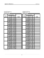
Page 64: ...an entire module with its connector is removed and reinstalled in a different module slot the system will not properly recognize the data being received Module Position 1 Record on the circuit directo...

Page 65: ...r terminal is identified with the acceptable input There are eight positions for each slot even though some modules accept fewer devices Figure 57 Modular Console System Circuit Directory MODULE TYPE...

Page 66: ...Mag Probe 2 Yes Ground temperature thermistor When using volumetric line leak detection VLLD only one ground temperature thermistor is needed per site and the thermistor must be wired to thermistor p...

Page 67: ...Device Wires Observe Polarity Mag Probe 2 Yes Interstitial sensor for fiberglass steel tanks 2 No Sump sensor 2 No Discriminating dispenser pan sensor 2 No Discriminating containment sump sensor 2 No...

Page 68: ...sensors for fiberglass steel tanks 2 No Sump sensor 2 No Position Sensitive Sensor 2 No Discriminating dispenser pan sensor 2 No Discriminating containment sump sensor 2 No Hydrostatic sensor for all...

Page 69: ...Device Wires Observe Polarity 4SITE solid state discriminating dispenser pan sensor 3 Yes 4SITE solid state discriminating containment sump sensor 3 Yes SENSOR MAXIMUM SENSOR OUTPUT RATINGS 13 VDC 20...

Page 70: ...Device Wires Observe Polarity 4SITE discriminating Interstitial sensor for fiberglass tanks 2 Yes Micro sensor 2 Yes Solid state dispenser pan sensor 2 Yes Solid state containment sump sensor 2 Yes SE...

Page 71: ...ndwater Sensor Interface module as shown in Figure 63 Device Wires Observe Polarity 4SITE Groundwater Sensor 3 Yes GROUND WATER SENSOR MAXIMUM SENSOR OUTPUT RATINGS 15 VDC 15 AMP F G W F G W F G W F G...

Page 72: ...the Vapor Sensor Interface module as shown in Figure 64 Device Wires Observe Polarity Vapor Sensor 3 Yes VAPOR SENSOR MAXIMUM SENSOR OUTPUT RATINGS 15 VDC 15 AMP V G W V G W V G W V G W V G W VAPOR S...

Page 73: ...trinsically Safe bay module is covered in the PLLD Site Prep and Installation Manual which is shipped with that system Device Wires Observe Polarity Mag Sensor 2 Yes ISD Vapor Flow meter 2 Yes ISD Vap...

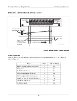
Page 74: ...used for flow control Alarm relays provide only a momentary closure and cannot actuate flow control devices such as valves and pump motor relays for extended periods of time Connect the wires from ea...

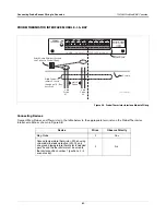
Page 75: ...conductors to the appropriate input terminals on the module Figure 67 I O Combination Module Wiring INPUT I O COMBINATION MODULE RELAY consoles iocmw eps Console Attach Cable Shield to Ground Lug Clo...

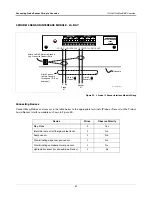
Page 76: ...of two 14 AWG conductors to the appropriate input terminals on the module Figure 68 Pump Relay Monitor Module Wiring Console consoles prmodulerj2 eps INPUT RATING 240VAC 0 15AMP MAX PUMP RELAY MONITO...

Page 77: ...ith Pressure Line Leak Detection 576013 499 Line Leak Interface Module Required with Volumetric Line Leak Detection 576013 765 WPLLD Controller Module Required with Wireless Pressurized Line Leak Dete...

Page 78: ...rd and an integral printer TCP IP Interface Module allows communication between a console and a PC over the internet DISPENSER INTERFACE MODULES DIMS CONSOLES W BIR ONLY BIR equipped consoles must be...

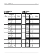
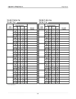
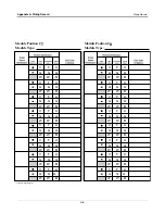
Page 79: ...ify record and maintain these wiring relationships MODULE POSITION The slot in the intrinsically safe bay of the console where this module is installed See the Circuit Directory located on the inside...

Page 80: ...F G W A G B V G W F G W A G B V G W F G W A G B V G W F G W A G B V G W F G W A G B V G W F G W A G B Module Position Module Type Module Position Module Type V G W F G W A G B V G W F G W A G B V G W...

Page 81: ...F G W A G B V G W F G W A G B V G W F G W A G B V G W F G W A G B V G W F G W A G B V G W F G W A G B Module Position Module Type Module Position Module Type V G W F G W A G B V G W F G W A G B V G W...

Page 82: ...F G W A G B V G W F G W A G B V G W F G W A G B V G W F G W A G B V G W F G W A G B V G W F G W A G B Module Position Module Type Module Position Module Type V G W F G W A G B V G W F G W A G B V G W...

Page 83: ...F G W A G B V G W F G W A G B V G W F G W A G B V G W F G W A G B V G W F G W A G B V G W F G W A G B Module Position Module Type Module Position Module Type V G W F G W A G B V G W F G W A G B V G W...

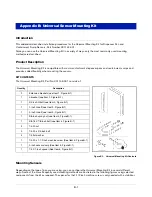
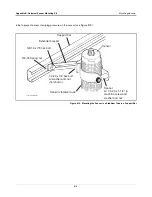
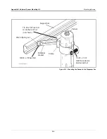
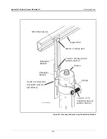
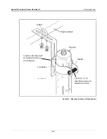
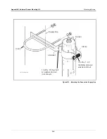
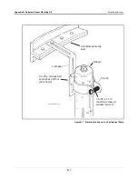
Page 84: ...the type of pan you are using you can configure the Universal Mounting Kit in several different ways Some of the more frequently used mounting methods are illustrated in the following figures using s...

Page 85: ...or see Figure B 2 Figure B 2 Mounting the Sensor in a Stabilizer Tube to a Support Bar Sensor stabilizer tube Sensor Support bar sensors snstbtb eps Spacer w 1 4 20 x 1 1 2 lg machine screw and washer...

Page 86: ...rs B 3 Figure B 3 Mounting the Sensor in the Dispenser Pan sensors mntsndp eps Sensor Clamp Extender bracket Support bar 3 8 16 Spring nut 3 8 16 x 7 8 hex bolt 1 4 20 x 3 4 hex bolt w washer and nut...

Page 87: ...nsor using Two Extension Brackets 3 8 16 Spring nut Support bar Extension bracket Extension bracket Clamp sensors extbkt eps Sensor 1 4 20 x 3 4 hex bolt w washer and nut 3 8 16 x 7 8 hex bolt 1 4 20...

Page 88: ...Kit Mounting Sensors B 5 Figure B 5 Mounting the Sensor to Rigid Conduit U Bolt U bolt L bracket Clamp Sensor Rigid conduit sensors snlbkt eps 1 4 20 x 3 4 hex bolt w washer and nut not shown 1 4 20 x...

Page 89: ...ing Kit Mounting Sensors B 6 Figure B 6 Mounting the Sensor to a Supply Line Supply line U bolt L bracket Sensor Clamp sensors snsupln eps 1 4 20 x 3 4 hex bolt w washer and nut not shown 1 4 20 x 1 1...

Page 90: ...it Mounting Sensors B 7 Figure B 7 Mounting the Sensor in a Containment Sump Clamp L bracket Sensor Containment sump wall sensors sncntmnt eps 1 4 20 x 3 4 hex bolt w washer and nut not shown 1 4 20 x...

Page 91: ...For technical support sales or other assistance please visit www veeder com...

Reviews: