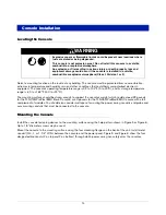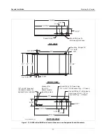
Introduction
Permissible Console Input/Output Connections
5
Permissible Console Input/Output Connections
TLS-300/PROPLUS/EMC BASIC CONSOLES
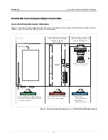
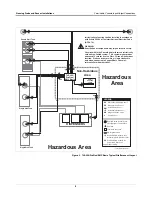
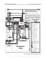
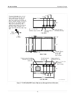
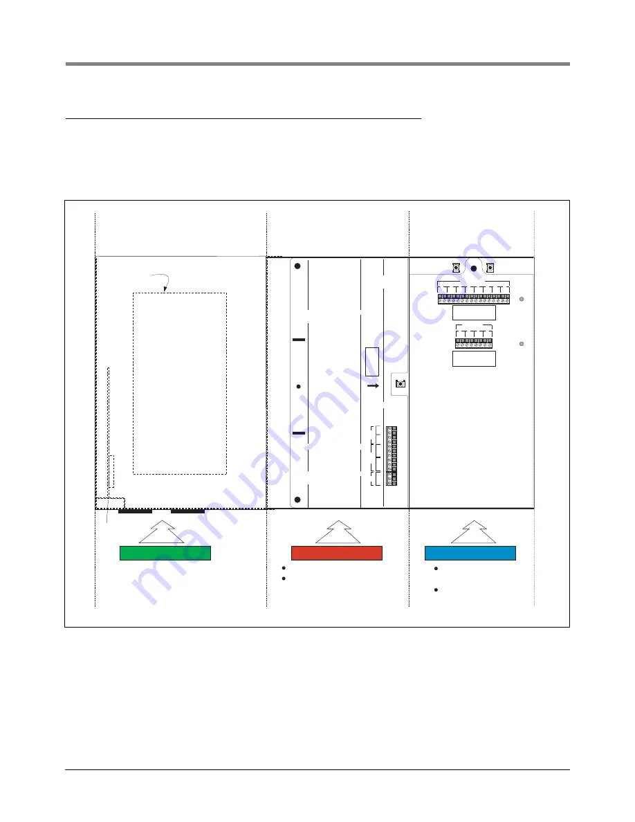
Figure 1 illustrates the permissible devices that can be connected to the console. Note that the number of inputs/
outputs in your console may differ from those shown below.
Figure 1. Permissible Inputs/Outputs by Area - TLS-300/ProPlus/EMC Basic Console
L
G
N
AC
NC
NO
C
2
NC
NO
C
1
RELAY
+
-
2
+
-
1
INPUT
BARRIER
GROUND
RELAY
RATINGS:
FORM C
CONTACTS
120 VAC,
2A Max; or
24 VDC,
2 A Max.
WARNING: TO INSURE
INTRINSIC SAFETY,
THIS COVER MUST
NOT BE REMOVED.
MAXIMUM PROBE
OUTPUT RATINGS:
13 VDC, .20 AMP.
+ - + - + - + -
1
2
3
4
PROBE
MAXIMUM SENSOR
OUTPUT RATINGS:
13 VDC, .20 AMP.
+ -
+ - + - + -
5
6
SENSOR
+ - + -
+ - + -
7
8
1
2
3
4
consoles\30-003.eps
Optional printer
Conduits attached to this area must
only contain wiring to probes and
sensors (see list below)
Conduits attached to this area must
only contain wiring to the inputs
approved for this area
(see list below)
WARNING: TO INSURE INTRINSIC SAFETY,
THIS COVER MUST NOT BE REMOVED.
Two solid state or switch inputs
Two Form-C relay outputs
Communications Area
3
1
2
Primary RS-232 Port (DB-25 Female)
1
2
Auxiliary RS-232 Port (DB-25 Female)
3
Comm module option
Power Area
Power Area
Intrinsically Safe Area
Sensor Inputs
(8 max per console)
Probe inputs
(8 max per console)


