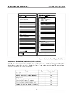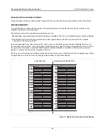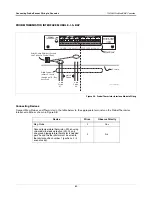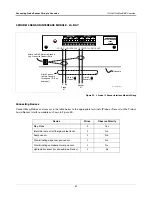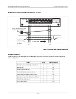
Connecting Probe/Sensor Wiring to Consoles
TLS-
3
00/ProPlus/EMC Basic Consoles
57
CONNECTING DEVICES TO POWER AREA I/O TERMINALS
Relay Outputs
Depending on the model console installed, you may have one or two Form-C relay outputs which you can connect
to overfill alarms and external audible/visual warning devices. Note – there are important output relay connection
restrictions:
1.
Do not connect output relays to a device that draws more than 2 amperes of current. Output power: output
relay contact, resistive load - 120 Vac, 2 A max.; or 24 Vdc, 2 A max.
2. Alarm relays cannot be used for flow control. Alarm relays provide only a momentary closure and cannot
actuate flow control devices such as valves and pump motor relays for extended periods of time.
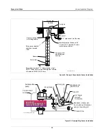
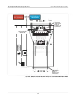
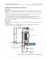
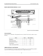
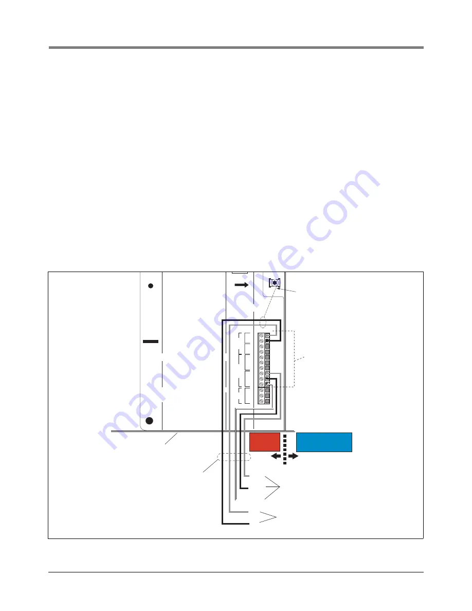
Connect the wires from the external device to the appropriate RELAY connector(s) on the I/O terminal block [see
2-relay output version in Figure 55].
External Inputs
The INPUT 1 and 2 terminals can accept two dry-contact switch closure inputs from an external device such as a
backup generator.
For each external input, connect a shielded cable consisting of two #18 AWG conductors to the INPUT
connectors on the I/O terminal block [see Figure 55].
.
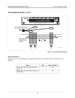
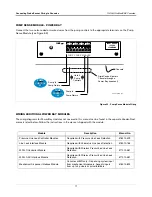
Figure 55. Example of Wiring I/O Devices to a TLS-300/ProPlus/EMC Basic Console
L
G
N
AC
NC
NO
C
2
NC
NO
C
1
RELAY
+
-
2
+
-
1
INPUT
BARRIER
GROUND
WARNING: TO INSURE
INTRINSIC SAFETY,
THIS COVER MUST
NOT BE REMOVED.
Rigid Conduit (enters through
a Power Area knockout)
Bottom of
console
NC
NO
C
Relay Output Wiring
#14 AWG
-
+
External Input Wiring
#18 AWG
Shielded Cable
Attach cable shield
to ground lug
I/O Terminal Block
POWER
AREA
POWER
AREA
INTRINSICALLY
SAFE AREA

