Connecting Probe/Sensor Wiring to Consoles
TLS-
3
50/ProMax/EMC Consoles
62
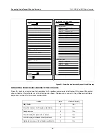
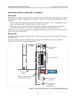
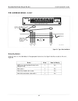
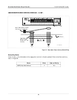
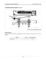
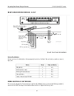
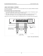
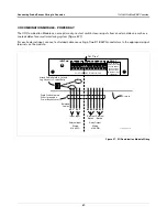
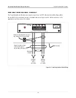
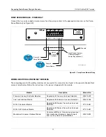
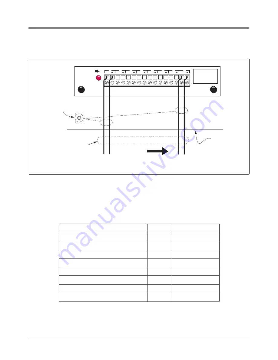
INTERSTITIAL SENSOR INTERFACE MODULE - I.S. BAY
Figure 60. Interstitial Sensor Interface Module Wiring
Connecting Devices
Connect sensors in the table below to the appropriate terminals on the Interstitial Sensor Interface module as
shown in Figure 60.
Device
Wires
Observe Polarity
Interstitial sensors for fiberglass/steel tanks
2
No
Sump sensor
2
No
Position-Sensitive Sensor
2
No
Discriminating dispenser pan sensor
2
No
Discriminating containment sump sensor
2
No
Hydrostatic sensor (for all double-wall tanks)
2
No
Oil/water separator sensor
2
No
CSTP Liquid Switch
2
No
SENSOR
MAXIMUM SENSOR
OUTPUT RATINGS:
15 VDC
.15 AMP
+
+
+
+
+
+
+
+
1
2
3
4
5
6
7
8
INTERSTITIAL SENSOR INTERFACE MODULE
consoles\isimwir.eps
Sensor
#1
Sensor
#8
Up to 8 sensors
Console
Attach Cable Shields to Ground
Lug Closest to Conduit Entry
Rigid Conduit
(enters Console
through an I.S. Bay
knockout)

