A-1
Appendix A: Wiring Record
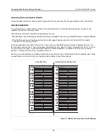
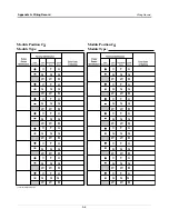
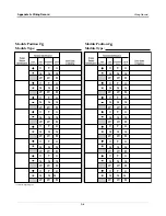
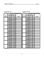
Wiring Record
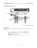
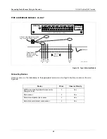
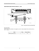
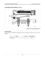
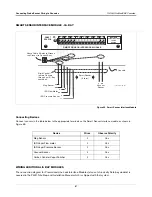
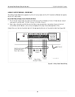
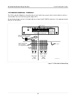
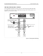
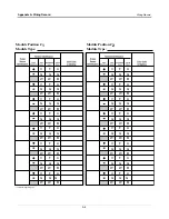
The wiring record forms in this appendix are intended for the installer’s use to accurately record the wiring scheme
and wiring identification for probes and sensors connected to the console. A definition of each record heading is
given below.
NOTE:
Failure to identify and maintain the relationship of wiring between probe and sensor locations and their
positions on console module connectors could result in the incorrect identification of a leak type or leak location,
or improper system operation. It is critical that you properly identify, record, and maintain these wiring relationships.
MODULE POSITION
The slot in the intrinsically safe bay of the console where this module is installed. (See the Circuit Directory located
on the inside of the console’s right-hand door.)
MODULE TYPE
Enter the type of module installed in this slot, i.e., Probe #1, Vapor Sensor - NW Corner.
PROBE/SENSOR IDENTIFICATION
Identify the device connected to this module location, i.e., Tank #1 Probe, Vapor Sensor - NW corner.
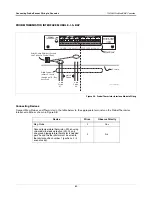
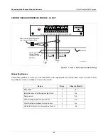
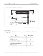
TERMINAL IDENTIFICATION
Probe and interstitial sensor connectors have 2 terminals per probe or sensor position (+ and –). Vapor sensor,
groundwater sensor, and Type B sensor connectors have 3 terminals per sensor.
COLOR CODE OR MARKING
Enter the color or marking that identifies the probe or sensor wire connecting to this module terminal.

