background image

10-9

10  

 Pressurized Line Leak Detection

Pressure Offset

Pressure Offset

New transducers are now factory sealed and their internal chamber cannot be equalized to atmospheric pressure 
by opening a vent screw as in the past. The Pressure Offset test procedure described in this section 

must

 be 

performed when using new PLLD transducers with serial numbers of 100,000 or above, in sites located at 
altitudes above 2,000 feet (609 m). Note: this procedure can also be used with transducers having serial numbers 
below 100,000 instead of using the vent screw to equalize pressure.

Table 10-1 illustrates approximate absolute pressures that are for reference only. The transducer’s actual reading 
may vary slightly due to its construction, A/D conversion, head pressure in the lines, etc. 

Before this procedure is performed, the pressure in the line MUST be vented to zero. It is recommended that this 
procedure be performed immediately after installing the transducer, before energizing the STP.

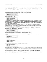
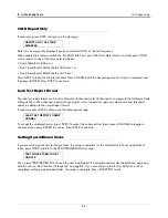
The first step is to vent the line(s). The second step is to go to the Diagnostic Mode and run a Pressure Offset Test 
for each transducer to determine its Pressure Offset value. The third step is to return to the Setup Mode and enter 
the Pressure Offset determined in the tests, for each transducer.

VENTING THE LINE

1. Turn Off, lock out, tag power to the STP.

2. Vent the line to zero. 

3. Reseal the line.

4. Turn On power to the STP. Follow the procedure below.

Table 10-1. Reference of Absolute Pressure Offsets at Various Altitudes

Altitude 

ft (m)

Atmospheric Pressure Offset 

psi (kPa)

Sea level - 2000 (609)

No Change

2000 - 3000 (609 - 914)

+1 (+6.9)

3000 - 4000 (914 - 1219)

+1.5 (+10.3)

4000 - 5000 (1219 - 1524)

+2.0 (+13.8)

5000 - 6000 (1524 - 1829)

+2.5 (+17.2)

6000 - 7000 (1829 - 2134)

+3.0 (+20.7)

7000 - 8000 (2134 - 2438)

+3.4 (+23.4)

8000 - 9000 (2438 - 2743)

+3.8 (+26.2)

9000 - 10,000 (2743 - 3048)

+4.2 (+28.9)

10,000 - 12,000 (3048 - 3658)

+4.6 (+31.7)

12,000 - 14,000 (3658 - 4267)

+5.4 (+37.2)

14,000 (4267) - above

+5.7 (+39.3)

OFF

Summary of Contents for TLS-350 Series

Page 1: ...Manual No 576013 623 Revision AM System Setup Manual TLS 3XX Series Consoles Software Version X33...

Page 2: ...and Conditions VEEDER ROOT S PREFERRED CARRIER 1 Contact Veeder Root Customer Service at 800 873 3313 with the specific part numbers and quantities that were missing or received damaged 2 Fax signed...

Page 3: ...r to Applying AC Power to the Console Security Code Enable Disable 4 1 TLS 300 Consoles 4 1 TLS 350 Consoles 4 1 Battery Backup 4 6 Applying AC Power to the Console 4 6 5 System Setup Programming Guid...

Page 4: ...st Needed Warnings and Alarms 5 12 Remote Printer Page Eject 5 13 Print TC Volumes 5 13 Temperature Compensation Value 5 13 Tanker Load Report International Option 5 14 Stick Height Offset Internation...

Page 5: ...6 10 Auto Dial Method All Phones Single Phone 6 11 Auto Dial Frequency Specific Date 6 11 Auto Dial Frequency Annually 6 12 Auto Dial Frequency Monthly 6 13 Auto Dial Frequency Weekly 6 13 Auto Dial...

Page 6: ...h Tank Chart Security Enabled 7 9 Meter Data Present 7 11 Vapor Loss Factor International Option 7 11 End Factor 7 12 Calibration Update 7 12 Float Size 7 13 Water Warning 7 14 High Water Limit 7 15 W...

Page 7: ...ort Format 8 9 Setting Up Additional Tanks 8 9 9 Fuel Management Selecting the Fuel Management Function 9 1 Delivery Warning Days 9 1 Daily Time to Print Fuel Management Report 9 1 Average Daily Sales...

Page 8: ...r each Transducer 11 5 Entering the Pressure Offset Value for each Transducer 11 6 Tank Selection 11 6 Selecting a Dispense Mode 11 6 Setting Up Additional WPLLDs 11 7 12 Volumetric Line Leak Detectio...

Page 9: ...Relay Monitor Relay Input 16 2 Pump Relay Monitor Delay Input 16 2 17 Reconciliation Setup Dispenser Module Data String 17 1 Automatic Daily Closing 17 1 Automatic Shift Closing 17 2 Periodic Reconci...

Page 10: ...Up Additional 2 Wire C L Sensors 21 3 22 3 Wire C L Sensor Setup Selecting the 3 Wire C L Sensor Setup Function 22 1 3 Wire C L Sensor Configuration 22 1 How the System Configures 3 Wire C L Sensors 2...

Page 11: ...e Disable Setup Selecting the PLLD WPLLD or VLLD Line Disable Setup Function 25 1 Alarm Assignment Notes 25 1 In Tank Alarms 25 1 Remaining Alarm Groups 25 2 Liquid Sensor Alarms 25 3 Vapor Sensor Ala...

Page 12: ...Switch and DIP Switch Location TLS 350 Consoles with ECPU Board 4 5 Figure 7 1 Relative Positions of Tank Alarm Limits 7 14 Figure 7 2 Siphon Manifolded Tanks 7 20 Figure 7 3 Line Manifolding A Siphon...

Page 13: ...ication Level 2 3 Contractors holding valid Technician Certifications are approved to perform installation checkout startup programming and operations training system tests troubleshooting and servici...

Page 14: ...ask someone who does ELECTRICITY High voltage exists in and is supplied to the device A potential shock hazard exists WARNING Heed the adjacent instructions to avoid damage to equipment property envi...

Page 15: ...ys They allow you to access and print data start and stop in tank leak test procedures program the system test system operation and review diagnostic information See Using the Operating Keys on page 2...

Page 16: ...lso selectable Note This key is available in consoles with Version 27 and higher software and is functional only if the Maintenance History or Maintenance Tracker feature enabled Using the Operating K...

Page 17: ...ter data revise existing data or change an entry ENTER ENTER completes a selection or enters data into a function It is also used to start certain func tions such as leak tests BACKUP BACKUP lets you...

Page 18: ...and enter the required character as described When all the characters have been entered press ENTER If you enter an incorrect character you may use the arrow keys to move the cursor to the character...

Page 19: ...headers and when selecting certain parameters such as module configurations The step by step setup instructions will identify when this function should be used The decimal is used in numeric entries a...

Page 20: ...e Leak Setup WPLLD Line Leak Setup Line Leak Detector Setup VLLD Line Leak Test Setup Line Leak Lockout Setup Pump Sensor Setup Pump Relay Monitor Setup Reconciliation Setup Liquid Sensor Setup Vapor...

Page 21: ...c Dlvy Var Rpts Disable Enable STEP Daily Book Dlvy Var Rpts Disable Enable STEP Weekly Book Dlvy Var Rpts Disable Enable STEP Periodic Book Dlvy Var Rpts Disable Enable STEP Daily Var Analy Rpts Disa...

Page 22: ...peat for each board Baud Rate Parity Stop Bit Data Length Dial Type Answer On Code Modem Setup String Dial Tone Interval DTR Normal State STEP Auto Transmit Setup Transmit Message Setup Auto Transmit...

Page 23: ...T SETUP STEP Delivery Warn Days XX X STEP Fuel Management Auto Print STEP Average Daily Sales FUNCTION IN TANK LEAK TEST SETUP STEP Test Method Single Tank All Tanks STEP Test Frequency On Date Annual...

Page 24: ...EP Blend Partners FUNCTION WPLLD LINE LEAK SETUP STEP Line Config Module 1 up to 3 STEP WPLLD Line Label STEP Piping Type STEP Line Length STEP 0 2 gph 0 76 lph Test Disabled Repetitive Monthly Manual...

Page 25: ...Shift 2 Closing Time STEP Auto Shift 3 Closing Time STEP Auto Shift 4 Closing Time STEP Periodic Reconciliation Mode Monthly Rolling Length STEP Periodic Reconciliation Alarm Disabled Enabled STEP Per...

Page 26: ...ngle Groundwater Alarms None All Single 2 Wire CL Type A Alarms None All Single 3 Wire CL Type B Alarms None All Single Power Side DIM Alarms None All Single Reconciliation Alarms None All Single PLLD...

Page 27: ...ide DIM Alarms None All Single Reconciliation Alarms None All Single PLLD Alarms None All Single WPLLD Alarms None All Single Comm Side DIM Alarms None All Single Pump Relay Monitor Alarms None All Si...

Page 28: ...able the security code feature and require entering of the security code s for front panel and or RS 232 system setup access make sure that switches 3 and or 4 on DIP switch S2 are in the Closed posit...

Page 29: ...or numbered boxes 1 Maintenance Report white key 3 Alphanumeric keypad 2 Maintenance Tracker blue key 4 Operating keypad consoles keypad eps MODE BACKUP FUNCT TION PRINT CHANGE STEP PAPER FEED ENTER Q...

Page 30: ...ion 5 DIP switch 1 can be in either position It is shown in closed position open side up number side down 2 Front Panel Security Code DIP Switch 4 6 Switch S2 3 RS 232 Security Code DIP Switch 3 7 S1...

Page 31: ...Legend for numbered boxes 1 CPU Board 5 DIP Switch 4 not used 2 Front Panel Security Code DIP Switch 1 6 Front Panel Display DIP Switch 3 3 Battery Backup Switch S1 Shown in ON position up 7 RS 232 S...

Page 32: ...Board Legend for numbered boxes 1 ECPU board 5 DIP switches 1 4 shown in the OPEN position open end down 2 View Front Panel Display DIP Switch 3 6 Battery Backup Switch SW1 Shown in OFF position down...

Page 33: ...2 The console front panel display will cycle through the following screens NOTE if you enabled the HRM feature see TLS 350 Consoles on page 4 1 the system date time format will default to DD MM YY HH...

Page 34: ...the ALARM TEST key to silence the audible alarm Slide the Battery Backup switch S1 or SW1 to the ON position After a few seconds the alarm light will go out and the front panel display will read 4 Yo...

Page 35: ...nces may change Multiple Choice Entries The setup procedure mentioned in this manual instructs you to press the STEP key to accept a default value and move to the next setup parameter When you are off...

Page 36: ...re English Dutch English French English Finnish English German English Greek English Italian English Japanese English Polish English Portuguese English Russian English Spanish English Swedish English...

Page 37: ...continue Setting the Date and Time Format If necessary press STEP until you see the message To accept the format shown press STEP The system displays the SET TIME message Available date time formats...

Page 38: ...the ENTER STATION HEADER message Enter up to 20 characters for the first line Press ENTER The system confirms your entry with the message To enter additional header lines press STEP and repeat the ab...

Page 39: ...R Printouts press CHANGE ENTER then STEP Daily BIR Printouts If necessary press STEP until you see the message Daily BIR Printouts enabled causes a BIR report to print at the end of the day s last shi...

Page 40: ...ode Operating Mode Variance reports are similar to the reconciliation reports generated for BIR except they also show ticketed book delivery volume Delivery Variance Reports show the difference betwee...

Page 41: ...until you see the message To enable Weekly Book Variance Reports press CHANGE ENTER then STEP PERIODIC BOOK VARIANCE REPORTS If necessary press STEP until you see the message To enable Periodic Book V...

Page 42: ...warning or a specified number of days ENABLE TANK PERIODIC TEST NEEDED WARNINGS AND ALARMS To enable Tank Test Needed Periodic Warnings press STEP The system displays the message Press CHANGE and ent...

Page 43: ...or conducted in a specified number of days 0 to 365 and activate an alarm if a test has not been passed after a warning or a specified number of days To keep Tank Annual Test Needed Warnings disabled...

Page 44: ...d message Line Re Enable Method If necessary press STEP until you see the message This feature lets you choose how to re enable a line shut down by a failing line leak test To re enable a shutdown lin...

Page 45: ...tem to alarm if a test has not been passed This number should be higher than the number you set for the warning Press ENTER The system displays the message Press STEP The system displays the Line Annu...

Page 46: ...not been passed 0 to 365 Press ENTER The system displays the message Press STEP The system displays the message The default value is 355 days If you do not want to accept the default press CHANGE Ente...

Page 47: ...nsation Value The system allows you to enter the temperature compensation TC reference temperature for all volume calculations This temperature is determined by your location In the U S the reference...

Page 48: ...that makes the probe height reading appear to be the same as the stick height reading Stick height offset will not be used for volume calculation If this feature is enabled you must enter the stick he...

Page 49: ...the CSLD option then press ENTER Precision Line Test Auto Confirm These Auto Confirm selections reduce the risks of false 0 2 and 0 1 gph 0 76 and 0 38 lph line test results However enabling these op...

Page 50: ...art Time The End Date message appears Press CHANGE then ENTER to select another End Date Press ENTER to accept your selected End Date The End Time message appears Press CHANGE then ENTER to select ano...

Page 51: ...console This feature lets you enter a delay of from 5 to 999 hours before posting a Block DIM Transaction Alarm Press CHANGE enter the desired delay then press ENTER to confirm your choice Enter 000...

Page 52: ...ected maintenance alarms Maintenance History enable date time of enable Maintenance History disable date time of disable Service codes service code date time entered Note Service codes can be found in...

Page 53: ...ion and features can be customized Your custom labels replace the system generated display print alarm labels that are used in display messages printouts and RS 232 reports only Alarm labels used in A...

Page 54: ...e Press CHANGE and ENTER to access available System Alarms or STEP to move through the alarm sets In Tank alarms Liquid Sensor alarms etc When making changes standard setup entry procedures apply you...

Page 55: ...Label ID Code Type Num Autodial Alarm Label System Alarm PAPER OUT 01 01 N A PRINTER ERROR 01 02 WRONG SOFTWARE WARNING 01 03 BATTERY IS OFF 01 04 TOO MANY TANKS 01 05 SYS SECURITY WARNING 01 06 ROM...

Page 56: ...L TEST FAIL 02 15 ANNUAL FAIL PER TST NEEDED WRN 02 16 PER NEED WRN ANN TST NEEDED WRN 02 17 ANN NEED WRN PER TST NEEDED ALM 02 18 PER NEED AL ANN TST NEEDED ALM 02 19 ANN NEED AL TANK TEST ACTIVE 02...

Page 57: ...NPUT NORMAL 05 02 N A EXTERN INPUT ALARM 05 03 CLOSED VLLD Alarm SETUP DATA WARNING 06 01 N A LLD SELF TEST FAIL 06 02 N A LINE LEAK SHUTDOWN 06 03 SHUTDOWN LINE LEAK TEST FAIL 06 04 N A SELF TEST INV...

Page 58: ...WARNING 14 04 ALARM CLEAR WARNING DELIVERY REPORT WRN 14 05 DELIVERY REPORT WRN Power Side DIM MDIM 18 or Communication Side DIM EDIM BDIM 19 DISABLED DIM ALARM for type see alarm category 02 DISABLE...

Page 59: ...RNING 26 01 N A GROSS LINE FAIL 26 02 GROSS FAIL PERIOD LINE FAIL 26 03 PERIOD FAIL PER TST NEEDED WRN 26 04 PER NEED WN PER TST NEEDED ALM 26 05 PER NEED AL WPLLD OPEN WARN 26 06 OPEN ALARM WPLLD COM...

Page 60: ...MP WARN RELAY ACTIVE 28 13 RELAY ACTIV INSTALL ALARM 28 14 INSTALL ALM SENSOR FAULT WARN 28 15 SNSR FLT WN VACUUM WARNING 28 16 VACUUM WARN NO VACUUM ALARM 28 17 NO VAC ALM Pump Relay Mon itor Alarm S...

Page 61: ...ny deliveries that occur when the TLS is in a Service Notice session will not go into the standard delivery history or BIR delivery history 5 If Delivery Override is disabled then any deliveries that...

Page 62: ...oup of five inventory alarms to the units you select here Note Changing the alarm inventory unit type configuration will set all inventory alarm thresholds to zero for all tanks If the inventory alarm...

Page 63: ...e to change the remaining four Inventory Alarms Press STEP to continue System Beeper If necessary press STEP until you see the message If you want to disable the console beeper press CHANGE Press ENTE...

Page 64: ...to accept NOTE A Setup Data Warning is posted from the time the Mass Density feature is enabled until a product density value is entered for that tank clearing the alarm ref Tank Density on page 7 4...

Page 65: ...n the Fiscal Height Security menu is displayed but cannot be changed Press ENTER Press CHANGE to enable this feature Press ENTER to accept Alarm Reduction If necessary press STEP until you see the mes...

Page 66: ...ommunications settings Baud Rate Parity Stop Bit etc for any board installed in the console s Comm Bay NOTE PORT SETTINGS INTERNATIONAL INSTALLATIONS WITH SITELINK MODEMS SiteLink modems are auto dete...

Page 67: ...sage Press STEP to continue PARITY Choose the parity that matches the external device connected to the module The choices are NONE ODD and EVEN To accept the parity shown on the message press STEP To...

Page 68: ...NOTE The above message appears only for systems equipped with a modem module To accept the system default of 1 ring press STEP To choose another value you can toggle the CHANGE key for 2 through 8 rin...

Page 69: ...2 1 on page 2 4 for instructions on entering these characters Press ENTER to select string and confirm selection e g Press STEP to continue DIAL TONE INTERVAL If you have a modem installed the system...

Page 70: ...of any of the following signals in tank alarm sensor alarm delivery start stop and input on off to an external device via the RS 232 or RS 485 port If you enable this feature the system provides thre...

Page 71: ...Auto Transmit message To set the Auto Delay Time press CHANGE and enter the delay time in seconds up to a maximum of 254 seconds Press ENTER to confirm your entry The system displays Press STEP to co...

Page 72: ...LOCATION After you set the receiver configuration the system displays the message Enter the location e g MAIN OFFICE FAX of the selected receiver To enter the location press CHANGE Enter up to 20 alph...

Page 73: ...em displays the message The system provides three choices for the type of receiver Teletype Facsimile or Computer A description of each follows Teletype the system calls the receiver telephone number...

Page 74: ...ccessfully The default condition is Off If you do not wish to receive confirmations press STEP The system returns to the PHONE DIRECTORY SETUP message To enable the feature press CHANGE and press ENTE...

Page 75: ...ssage D1 D2 etc press STEP The system displays the next type of report To include System Status reports for transmission to the selected receiver press CHANGE and press ENTER The system confirms you c...

Page 76: ...rt transmission frequency information for each receiver individually The screen examples shown in this procedure assume that you have selected All Phones If you choose Single Phone the phrase ALL RCVR...

Page 77: ...additional receivers to set up refer to the section entitled Setting Up the Frequency for Additional Receivers Single Phone Only on page 6 15 AUTO DIAL FREQUENCY ANNUALLY If necessary press STEP unti...

Page 78: ...NGE until the week during which you want to transmit the reports appears and press the Right Arrow key Press CHANGE until the day on which you want to transmit the reports appears Press ENTER to confi...

Page 79: ...e Press CHANGE and enter the time at which you want to transmit the reports Press the Right Arrow key to choose AM or PM Press ENTER to confirm your entry Press STEP to continue If you are using the A...

Page 80: ...ate Auto Dial Frequency instructions beginning on page 6 11 NOTE Do not press ENTER after changing the destination You must choose the Auto Dial Frequency as described in the previous sections before...

Page 81: ...Single Tanks press CHANGE twice Press ENTER to confirm your choice If ALL TANKS is selected the system displays Press STEP to specify the tanks for the next In Tank Alarm condition HIGH WATER Repeat t...

Page 82: ...arms to send ref Alarm List in Table 6 2 VAPOR SENSOR ALARMS If necessary press STEP until you see the message Select the Vapor Sensor Alarms to send ref Alarm List in Table 6 2 EXTERNAL INPUTS ALARMS...

Page 83: ...2 POWER SIDE DIM ALARMS If necessary press STEP until you see the message Select the Power Side DIM Alarms to send ref Alarm List in Table 6 2 RECONCILIATION ALARMS If necessary press STEP until you s...

Page 84: ...ct the Smart Sensor Alarms to send ref Alarm List in Table 6 2 PUMP RELAY MONITOR ALARM If necessary press STEP until you see the message Select Pump Relay Monitor Alarm ref Alarm List in Section 6 Ta...

Page 85: ...e beginning with the section entitled In Tank Alarms on page 6 16 RS 232 End of Message If necessary press STEP until you see the message This feature notifies the receiver that the message is complet...

Page 86: ...PROBE OUT WATER WARN DLVY NEEDED MAX PRODUCT GROSS FAIL PERIOD FAIL ANNUAL FAIL PER NEED WN ANN NEED WN PER NEED AL ANN NEED AL TEST NOTIFY NoIDLE TIME SIPHON BRK CSLD INCR ACCU WARN RECON WARN RECON...

Page 87: ...22 Liquid Sensor Alarms FUEL OPEN1 SHORT WATER WATER OUT HIGH LIQUID LOW LIQUID LIQ WARNING Vapor Sensor Alarms FUEL OPEN1 SHORT WATER WATER OUT HIGH LIQUID LOW LIQUID LIQ WARNING External Inputs Alar...

Page 88: ...S PSELF PER NEED WN ANN NEED WN PER NEED AL ANN NEED AL PER LINE PER LSELF PER PUMP PER PSELF ANN LINE ANN LSELF ANN PUMP ANN PSELF PRESS WARN PRESS ALM TST FLT GRS TST FLT PER TST FLT ANN FUEL OUT Gr...

Page 89: ...3 Wire C L Sensor Alarms FUEL OPEN1 SHORT WATER WATER OUT HIGH LIQUID LOW LIQUID LIQ WARNING Receiver Alarms SERVICE REPORT WARN ALARM CLEAR WARNING DELIVERY REPORT WRN NO DIAL TONE ALARM DEL NOTIFICA...

Page 90: ...ARM SHUTDOWN PERIOD FAIL ANN NEED WN ANN NEED AL LO PRES ALM HANDLE ALRM FUEL OUT LN EQ FAULT WPLLD Alarms GROSS FAIL PERIOD FAIL PER NEED WN PER NEED AL OPEN ALARM COMM ALARM SHUTDOWN ANN LN FAIL ANN...

Page 91: ...ARM WATER WARN Smart Sensor Alarms WATER ALARM HI LIQ WRN HI LIQ ALM LOW LIQ WRN LOW LIQ ALM TEMP WARN RELAY ACTIVE INSTALL ALM SNSR FLT WRN VACUUM WARN NO VAC ALM Pump Relay Monitor Alarm PUMP ALARM...

Page 92: ...ou specify which positions on a module are connected to probes the system establishes a number for each probe that corresponds to the probe s position on the module For example if there is a probe con...

Page 93: ...e UL UNLEADED will send UL To enter the type of fuel in the tank press CHANGE Enter an alphanumeric label for any system compatible fluid fuel Press ENTER to confirm your entry The system displays Pre...

Page 94: ...t U S Units Thermal Coefficient Metric Units AdBlue or DEF 0 00040 0 00022 Alcohol 0 00063 0 00114 Aviation Gas 0 00075 0 00135 Diesel fuel oil 2 DERV 0 00045 0 00081 Derv Biodiesel B20 0 00045 0 0008...

Page 95: ...low units are not entered Mass per unit volume at reference temperature density Specific Gravity API number A fourth way to enter Density is by entering the known Thermal Coefficient of the product in...

Page 96: ...the 100 full volume to profile the tank This selection is used for horizontally installed flat ended cylindrical tanks and should be selected when AccuChart is available for this type tank 4 Points T...

Page 97: ...e press STEP to continue To select another tank profile 4 pt 20 pt Linear or 50 pt press CHANGE until the desired profile is displayed Press ENTER If sure press CHANGE Press ENTER to confirm Full Volu...

Page 98: ...HART SECURITY DISABLED If you selected 50 points for Tank Profile and Tank Chart Security is disabled press STEP and the system displays A Viewing Height Volume Points At the display below Press ENTER...

Page 99: ...sary press STEP until you display the height volume point you want to remove Press CHANGE Press ENTER to confirm Press STEP and follow the above procedure to continue removing height volume points unt...

Page 100: ...to confirm your entry The system displays Press STEP to continue The Weights and Measures Officer presses CHANGE and enters the tank capacity Press ENTER to accept the value and press STEP to continu...

Page 101: ...Press STEP Press CHANGE enter the volume at this height Press ENTER to accept the entry Press STEP and follow the above procedure to continue adding height volume points until you are finished T1 VIEW...

Page 102: ...ng reported to the DIM i e meter data present then this parameter MUST be set to YES To enable the feature press CHANGE then ENTER to confirm your choice The system displays Press STEP to continue Vap...

Page 103: ...international installations CAL UPDATE will be PERIODIC if HRM is enabled see TLS 350 Consoles on page 4 1 IMPORTANT For proper setup and operation of this feature you should 1 Pressure test all lines...

Page 104: ...ilt and capacity If the customer changes the method from Never to one of the other methods the other method goes into effect immediately 1 For PLLD installations with line manifolded tanks the master...

Page 105: ...the selected tank press CHANGE Enter the limit in inches 5 0 maximum or millimeters 199 maximum depending on the units established in System Setup Press ENTER to confirm your entry The system displays...

Page 106: ...ces are Low default Medium High and Off The default filter setting of Low provides a quick response and will not inhibit a water alarm during a delivery In most applications it provides the quickest r...

Page 107: ...alarm warns when the level of fluid in the tank exceeds the volume you enter here Set this value at a level higher than the High Level Limit see Figure 7 1 Press CHANGE and enter the value Press ENTE...

Page 108: ...GE Enter the percent limit Press ENTER to confirm your entry The system displays Delivery Limit If necessary press STEP until you see the message Delivery Limit warns when the level of fluid in the ta...

Page 109: ...Alarm Limit press CHANGE Enter the limit in gallons from 1 to 99 or litres from 4 to 399 depending on the units set up in System Units Press ENTER to confirm your entry The system displays Sudden Loss...

Page 110: ...ure the distance in inches or millimetres from the probe riser to the center of the tank Record the distance in column F 7 Multiply column E by column F to determine Tank Tilt E X F Tank Tilt Value Re...

Page 111: ...siphon manifolded tank set You only need to enter this information for one of the tanks in the set The system automatically enters the information for the other tank s in the set Figure 7 2 Siphon Man...

Page 112: ...s line manifolded with Tank 1 itself in a siphon manifolded set you would press CHANGE until 01 appears you would press the Right Arrow key to move to the next field if another tank were in the line m...

Page 113: ...ess ENTER to confirm your entry The system displays Periodic Test Type If necessary press STEP until you see the message You can choose between Standard and Quick Choose Standard to run a 2 hour perio...

Page 114: ...STEP until you see the message The Gross Test Fail feature allows you to disable or enable an alarm that triggers when a 3 0 gph 11 3 lph leak test fails To disable the alarm press STEP The system dis...

Page 115: ...isplays the message Tank Test Siphon Break If necessary press STEP until you see the message NOTE This option requires that the siphon break valve be installed When on Tank Test Siphon Break allows th...

Page 116: ...ring HRM feature can be set to verify that HRM is enabled see TLS 350 Consoles on page 4 1 This is the average reconciliation variance over a 24 hour period If necessary press STEP until you see the m...

Page 117: ...ial If necessary press STEP until you see the message When the tank s volume drops below the entered Pump Threshold percentage pumping will switch over immediately to the next available tank in the li...

Page 118: ...the same setup information or you can choose to set up and run leak tests for single tanks If you choose Single Tank you may run overlapping tests simultaneously even though you enter separate setup...

Page 119: ...abled see TLS 350 Consoles on page 4 1 AUTOMATIC requires that the tank be assigned to a Line Leak Detector see Tank Selection on page 10 7 for PLLD Tank Selection on page 11 6 for WPLLD or Pipe Label...

Page 120: ...ek of June the system would display the message Press STEP to continue The system displays the START TIME message Follow the procedure under Leak Test Start Time on page 8 7 MONTHLY TEST To run the te...

Page 121: ...e tests daily press CHANGE four times then press ENTER in response to the ON DATE message The system displays the message Press STEP to continue The system displays the START TIME message Follow the p...

Page 122: ...you see CSLD on the display Press ENTER to confirm your choice Press STEP to display the message You can set the Pd Probability of Detection to 95 or 99 To accept the 95 value press STEP The system d...

Page 123: ...o activate CSLD evaporation compensation for a single tank press CHANGE Press ENTER to confirm your choice The following message displays The default for Stage II Vapor is YES To select No press CHANG...

Page 124: ...TEP until you see the message You can enable the test by entering a start time or leave the test disabled To leave the test disabled press STEP The system displays the TEST RATE message To enter a sta...

Page 125: ...ration of more than 2 hours Enter the test duration in hours and press ENTER to confirm your choice Press STEP to continue Leak Test Early Stop If necessary press STEP until you see the following mess...

Page 126: ...ns The enhanced report will have height water temperature percent volume rate and threshold values in addition to the normal report format If necessary press STEP until you see the following message T...

Page 127: ...g the Fuel Management Function To select Fuel Management Setup press FUNCTION until you see the message Press STEP until you see the setup screen that you want Delivery Warning Days If necessary press...

Page 128: ...to confirm your entry Press STEP to display the AVG SALES message for Mondays Press CHANGE enter the average daily sales for the selected day and product and press ENTER Press STEP Repeat the procedu...

Page 129: ...D Setup Press FUNCTION until you see the message Press STEP to continue Activating PLLDs This display allows you to activate up to six PLLDs In the active state PLLD attempts to conduct line leak test...

Page 130: ...ensure accurate line monitoring you must enter the piping type that is installed for this line The default is Enviroflex PP1501 Press CHANGE enter the correct pipe type press ENTER to confirm your ch...

Page 131: ...the 3 inch 76 mm size If you are not using 3 inch line enter 0 and press ENTER If you are using 3 inch line enter the length and press ENTER IMPORTANT When using the Fiberglass pipe type the unused s...

Page 132: ...hermal Expansion on page 7 3 Press STEP to continue Thermal Coefficient If you selected APT P175SC PETROTECHNIK UPP EXTRA 63 MM or OPW PISCES SP20 as the pipe type you must enter the product s thermal...

Page 133: ...t Duration setup is then observed Following the test blockout period the test sequence repeats after the next dispense This selection also enables manual 0 1 gph testing Note The Repetitive option is...

Page 134: ...ate or press CHANGE until the desired shutdown rate appears then ENTER to confirm your choice NOTE If you select a 0 1 gph 0 38 lph shutdown rate a failed 0 1 gph 0 2 gph 0 76 lph or 3 0 gph leak test...

Page 135: ...pumping will switch over immediately to the next available tank in the line manifolded set Pumping will continue from the current tank for another 10 seconds to avoid a disruption in dispensing durin...

Page 136: ...ays back and forth a pump must be running for 2 minutes before automatic pump switchover becomes enabled Press CHANGE to enable Active Switchover and ENTER to confirm If you selected Manifolded Altern...

Page 137: ...ero It is recommended that this procedure be performed immediately after installing the transducer before energizing the STP The first step is to vent the line s The second step is to go to the Diagno...

Page 138: ...si 34 5 kPa repeat the test If the Pressure Offset is again out of range either the line pressure is not completely vented or there is a hardware problem Refer to PLLD troubleshooting procedures for f...

Page 139: ...ress ENTER Before proceeding to Blend Partners enable Mechanical Blender for all lines Press CHANGE Press ENTER Setting Up Additional PLLDs If you have additional PLLDs to set up press STEP to return...

Page 140: ...12 WPLLD Setup Press FUNCTION until you see the message Press STEP to continue Activating WPLLDs This display allows you to activate up to a maximum of 9 WPLLDs In the active state a WPLLD attempts t...

Page 141: ...r the piping type that is installed for this line The default is Enviroflex PP1501 Press CHANGE enter the correct pipe type press ENTER to confirm your choice and continue Piping Length This display a...

Page 142: ...Disabled No manual or automatic 0 2 gph testing is allowed Repetitive After a dispense a 3 0 gph 11 3 lph test is run followed by a 0 2 gph test The test blockout period selected in Precision Test Du...

Page 143: ...te appears then ENTER to confirm your choice NOTE if you select a 0 1 gph shutdown rate a failed 0 1 gph 0 2 gph or 3 0 gph leak test will disable dispensing If you select a shutdown rate of 3 0 gph t...

Page 144: ...R and the results of the last test displays No Test Data Available message appears if this is the first test Press STEP To start the test press ENTER During the test this message appears The Pressure...

Page 145: ...e input for automatic in tank leak detection CSLD catastrophic leak testing and other features This step can only be used for tanks that are not already connected to a line leak detector This message...

Page 146: ...All pumps on the line are run Press CHANGE until your choice appears then press ENTER to continue Setting Up Additional WPLLDs If you have additional WPLLDs to set up press STEP to return to the WPLL...

Page 147: ...r press CHANGE in response to the LINE CONFIG message until the correct choice appears 1 to activate X to deactivate Press ENTER to confirm your choices The system displays NOTE Slot 1 is the slot at...

Page 148: ...message This step lets you choose the dispense mode of the tank s on which the Line Leak Detector has been installed The choices are STANDARD Only one pump feeds the line MANIFOLDED ALTERNATE1 The pu...

Page 149: ...fuel that is being dispensed Press STEP to continue Piping Length and Type If necessary press STEP until you see the message To enter the length of 2 inch 50 mm piping in the line press CHANGE Enter...

Page 150: ...e in the pipeline To enter the pump pressure press CHANGE Enter the pump pressure to the nearest whole number Refer to Table 12 1 for nominal pressures Table 12 1 Submersible Pump Nominal Pressures Pu...

Page 151: ...ge After the system conducts a line leak test the line leak detector also runs a pump side test for a pressure loss in the piping and connections between the in line check valve and the submersible pu...

Page 152: ...essage Press STEP to continue New Blender Protocol NBP Partner If necessary press STEP until you see the message The NBP New Blender Protocol Partner feature allows LLDs attached to lines where produc...

Page 153: ...the date Press ENTER to confirm your entry Setting Up Additional Line Leak Detectors If you have additional Line Leak Detectors to set up press STEP to return to the ENTER PIPE LABEL message Press TAN...

Page 154: ...can run line leak tests using the same test conditions frequency start time and test rate for all lines or you can establish different test conditions for each line To specify the same test conditions...

Page 155: ...ntinue The system displays the START TIME message Follow the procedure under Leak Test Start Time on page 13 4 ANNUAL TEST To run the tests annually press CHANGE and press ENTER in response to the ON...

Page 156: ...l the week during which you want to perform the test appears and press the Right Arrow key Press CHANGE until the day on which you want to perform the test appears Press ENTER to confirm the date Pres...

Page 157: ...low Leak Test Start Time If necessary press STEP until you see the message You can enable the test by entering a start time or leave the test disabled To leave the test disabled press STEP The system...

Page 158: ...ystem displays the following message Setting Up Additional Lines To set up line leak tests for additional lines press STEP to return to the TEST SINGLE LINE message Press TANK SENSOR to select the nex...

Page 159: ...ou to enter a Lockout Start Time and Lockout Stop Time The lockout period will begin and end at these times every day of the week Note By using a Daily schedule and entering the same Start and Stop Ti...

Page 160: ...ress ENTER The system confirms your choice with the message Press STEP to display the message If you want to change the lockout schedule number you can have up to seven individual lockout schedules pr...

Page 161: ...u want appears Press ENTER The system confirms your choice with the message Press STEP to display the message Press CHANGE and enter the lockout stop time Press the Right Arrow key to select AM or PM...

Page 162: ...ber for each pump that corresponds to its position on the module For example if there is a pump connected to inputs 3 and 4 of module 1 the pump connected to position 3 becomes S3 and the pump connect...

Page 163: ...w one at a time When the tank s volume drops below the entered Pump Threshold percentage pumping will switch over immediately to the next available tank in the line manifolded set Pumping will continu...

Page 164: ...low that of the alternate tank by the active switchover threshold amount the console automatically switches to the pump in the alternate tank Active switchover will continue as necessary until the dis...

Page 165: ...on a module are connected to which pumps the system assigns a number for each pump that corresponds to its position on the module For example if there is a pump connected to inputs 3 and 4 of module...

Page 166: ...e code number and label of the controlling relay e g Pump Sense PLLD WPLLD VLLD Pump Control Output I O Combo or 4 Relay For any of these entries if the pump continues to run after it is instructed to...

Page 167: ...Bay To enter a dispenser module data string press CHANGE enter a valid DIM description selected from the appropriate DIM Installation Manual The system accepts up to twelve alphanumeric characters how...

Page 168: ...e 5 5 and stored in memory To leave a shift closing time disabled press STEP The system displays the AUTO SHIFT CLOSING TIME message for the next shift To set a closing time for shift 1 press CHANGE a...

Page 169: ...ault is 1 00 of throughput plus 130 gallons 492 litres offset In the U S the EPA has set this default as a criteria not to be exceeded The Periodic Reconciliation Alarm is triggered when the alarm thr...

Page 170: ...sage Press STEP to continue Temp Compensation If necessary press STEP until you see the message This feature allows you to choose whether or not to calculate Business Inventory Reconciliation BIR volu...

Page 171: ...nk meter map Press ENTER to change the tank meter map and the system displays Press or to move to the field you want to change Then press CHANGE until the correct choice appears Press ENTER to confirm...

Page 172: ...the message Press STEP to return to the Disp Module Data String menu if DIM is installed or to Automatic Daily Closing menu if DIM is not installed or press ENTER to change the meter offset for the s...

Page 173: ...e installed in slots 3 and 6 the module in slot 3 automatically becomes module 1 and the module in slot 6 becomes module 2 As you specify which liquid sense wire positions on a module are connected to...

Page 174: ...Press STEP to continue Liquid Sensor Type If necessary press STEP until you see the message If necessary press CHANGE to display additional liquid sensor types see table below Sensor Type Entry Applic...

Page 175: ...d under ANNULAR SPACE in the liquid sensor category Then upon alarm this sensor can only be cleared through the CONFIRM CLEAR function in the Diagnostic Mode This is feature is only available if HRM i...

Page 176: ...ule in slot 3 automatically becomes module 1 and the module in slot 6 becomes module 2 As you specify which sensor positions on a module are connected to vapor sensors the system establishes a number...

Page 177: ...Press STEP to continue Vapor Threshold If necessary press STEP until you see the message The SENSOR THRESHOLD message lets you enter vapor levels to identify a leak or serious spillover and to trigger...

Page 178: ...D LEVELS To enter the vapor threshold for the selected sensor press CHANGE in response to the SENSOR THRESHOLD message Enter the vapor threshold value that you calculated based on the formula describe...

Page 179: ...or sensors to configure press STEP if necessary to return to the ENTER SENSOR LOCATION message Press TANK SENSOR to select another sensor and follow the procedures described above beginning with the s...

Page 180: ...nd 6 the module in slot 3 automatically becomes module 1 and the module in slot 6 becomes module 2 As you specify which sensor positions on a module are connected to groundwater sensors the system est...

Page 181: ...EW CORNER etc This information appears on sensor status and sensor alarm reports to make it easier to identify the location of the alarm Press ENTER to confirm your entry Press STEP to continue Ground...

Page 182: ...the module in slot 6 becomes module 2 As you specify which sensor positions on a module are connected to 2 Wire C L sensors the system establishes a number for each sensor For example if there is a 2...

Page 183: ...alarm Press ENTER to confirm your entry Press STEP to continue 2 Wire C L Sensor Type If necessary press STEP until you see the message Use this display to identify the selected sensor s type so the s...

Page 184: ...SUMP When you display the correct category press ENTER Setting Up Additional 2 Wire C L Sensors If you have additional sensors to configure press STEP until you see the ENTER SENSOR LOCATION message P...

Page 185: ...the module in slot 6 becomes module 2 As you specify which positions on a module are connected to 3 Wire C L sensors the system establishes a number for each sensor For example if there is a sensor in...

Page 186: ...ected sensor s mode so the system can properly interpret and report sensor information You can choose Standard mode or High Vapor mode In Standard mode the sensor alarms when it senses any hydrocarbon...

Page 187: ...g Up Additional 3 Wire C L Sensors If you have additional sensors to configure press STEP if necessary until you see the ENTER SENSOR LOCATION message Press TANK SENSOR to select another sensor and fo...

Page 188: ...and the module in slot 6 becomes module 2 As you specify which input positions on a module are connected to external devices the system establishes a number for each input position For example if an e...

Page 189: ...splay to define the type of input Standard Generator Pump Sense or Standard ACK that is connected to the selected input location Choose Standard for any input device connected for the purpose of using...

Page 190: ...ssage for the Input Type you selected External Input Emergency Generator Data If necessary press STEP until you see the message NOTE This message appears only if you chose GENERATOR for the External I...

Page 191: ...seconds to avoid a disruption in dispensing during the switch over see Pump Threshold on page 7 26 MANIFOLDED ALL PUMPS All pumps on the line are run MANIFOLDED ALTERNATE HT1 2 When a dispense starts...

Page 192: ...as necessary until the dispense ends To prevent rapid switching of the pump relays back and forth a pump must be running for 2 minutes before automatic pump switchover becomes enabled Press CHANGE to...

Page 193: ...ly becomes module 1 and the module in slot 13 becomes module 2 As you tell the system which relay positions on a module are connected to external devices the system establishes a number for each relay...

Page 194: ...f four output relay types STANDARD The On Off state is determined by assigned alarms warnings PUMP CONTROL OUTPUT Responds to a pump request received from an assigned Pump Sense module or Line Leak mo...

Page 195: ...ethod of assignment none all or single for each alarm condition NOTE You may assign more than one in tank alarm sensor alarm and external input to a relay and you may assign any in tank alarm sensor a...

Page 196: ...rect tank number appears press CHANGE and press ENTER The system confirms your entry for T1 with the message Continue to press TANK SENSOR to select additional tanks For example pressing TANK once wou...

Page 197: ...age Select the Liquid Sensor Alarms ref Alarm List in Section 6 Table 6 2 VAPOR SENSOR ALARMS If necessary press STEP until you see the message Select the Vapor Sensor Alarms ref Alarm List in Section...

Page 198: ...6 Table 6 2 RECONCILIATION ALARMS If necessary press STEP until you see the message Select Reconciliation Alarms ref Alarm List in Section 6 Table 6 2 PRESSURE LINE LEAK DETECTOR PLLD ALARMS If necess...

Page 199: ...Alarm List in Section 6 Table 6 2 When you have specified the assignment method for each Pump Relay Monitor Alarm condition press STEP If no other sensor or inputs are configured the system returns to...

Page 200: ...EP if necessary until the system returns to the message Press TANK SENSOR to choose another relay Set up the relay by repeating the procedures you followed for the previous relay Refer to the previous...

Page 201: ...s displayed on your screen You may assign more than one in tank alarm sensor alarm and external input to a line and you may assign any in tank alarm sensor alarm and external input to more than one li...

Page 202: ...onal tanks For example pressing TANK once would display the following message Repeat the steps described above to assign additional tanks to the line When you have assigned all the tanks you want to t...

Page 203: ...arm List in Section 6 Table 6 2 LINE LEAK ALARMS If necessary press STEP until you see the message Select Line Leak Volumetric Alarms ref Alarm List in Section 6 Table 6 2 GROUNDWATER SENSOR ALARMS If...

Page 204: ...URE LINE LEAK DETECTOR PLLD ALARMS If necessary press STEP until you see the message Select Pressure Line Leak Detector Alarms ref Alarm List in Section 6 Table 6 2 OPEN ALARM HANDLE ALRM LN EQ FAULT...

Page 205: ...m List in Section 6 Table 6 2 When you have specified the assignment method for each Pump Relay Monitor Alarm condition press STEP If no other sensor or inputs are configured the system returns to the...

Page 206: ...cessary until the system returns to the message Press TANK SENSOR to choose another line Set up the line by repeating the procedures you followed for the previous line Refer to the previous sections b...

Page 207: ...position 2 becomes s2 and the sensor in position 4 becomes s4 To specify whether position 1 is connected press CHANGE until the correct choice appears 1 if the position is connected X if it is not Pre...

Page 208: ...E NO UPGRADE NO WATER WARNING WATER HT 2 0 PROGRAMMABLE YES UPGRADE YES TEMPERATURE WARNING FLUID TEMP 12 5 PROGRAMMABLE YES UPGRADE NO Alarm Name Alarm Parameter Alarm is programmable yes no Alarm is...

Page 209: ...s that have been factory set to upgrade If necessary press CHANGE and enter the number of hours up to 9999 to delay upgrades Entering 0 disables the Alarm Upgrade Delay feature Press ENTER to confirm...

Page 210: ...lume between 1 and 500 is not entered Press CHANGE and enter the interstitial space volume Press ENTER to confirm your entry Press STEP to continue Steel Tank If this Vac Sensor is monitoring a steel...

Page 211: ...til you see the message Press STEP to continue Press PRINT to printout current VMC setup see example at right Add a VMC Serial Number If necessary press STEP until you see the message Press ENTER Ente...

Page 212: ...NK SENSOR repeatedly until the desired VMC displays Press CHANGE Press ENTER to confirm Press STEP Press CHANGE Press STEP REMOVE VMC SERIAL NUMBER PRESS ENTER x 1 111111 REMOVE VMC NO x 1 111111 REMO...

Page 213: ...uChart calibration will have to restart and won t be complete for 56 days Therefore if you plan to replace the ECPU board or the battery you should consider downloading all data setup and historical t...

Page 214: ...e console Off and then back On the system will wait 5 minutes before processing your request to restore archived setup data This delay is to allow all hardware to initialize If necessary press STEP un...

Page 215: ...he EEPROM press CHANGE then press ENTER The system confirms your choice with the message The system asks you to reconfirm your choice with the following message To abandon the clear process press STEP...

Page 216: ...ly Entering a Tank Tilt value is not recommended if the system is performing automatic Business Inventory Reconciliation and AccuChart Table A 1 lists offset values for various tank diametres probe of...

Page 217: ...Tilt Striker Plate Thickness 2 No offset 10 No offset 3 Probe 11 Probe 4 No striker plate 12 Thickness of striker plate 5 Tank Tilt Offset Value No Striker Plate 13 Tank Tilt Offset Value Striker Plat...

Page 218: ...ANGE If the value is negative press the key so that a minus sign appears on the display Enter the value as calculated according to the above procedures inches or millimetres depending on the units spe...

Page 219: ...equired Header Message 1 None Site Name Header Message 2 None Site Address Header Message 3 None Site Address Header Message 4 None Site Address Shift Time 1 Disabled Default Shift Time 2 Disabled Def...

Page 220: ...g UL UNLEADED Product Code 1 to 8 Default Thermal Coeff 000000 0 00126 Spirit 0 00300 LPG 0 00081 DV Tank Diameter 00000 As Tank Diameter Tank Profile 1 Point 1 Point Flat Ends 4 Point Shallow dished...

Page 221: ...nifold Tanks None Default Leak Min Annual 0 60 Periodic Test Type Standard Default Annual Test fail Al Disabled Default Periodic Test Fail Al Disabled Default Gross Test Fail Disabled Default Ann Test...

Page 222: ...None Site Address Shift Time 1 Disabled Default Shift Time 2 Disabled Default Shift Time 3 Disabled Default Shift Time 4 Disabled Default Shift BIR Prn Disable Default Daily BIR Prn Enabled Default T...

Page 223: ...lt Stick Height Offset Disabled Disabled H Protocol Format Height Default Precision Test Duration Precision Line Test Auto Confirm Enabled Daylight Savings Time Enabled MAR WK6 SUN 03 00AM OCT WK6 SUN...

Page 224: ...75 Tank Diameter Point 3 00000 50 Tank Diameter Point 4 00000 25 Tank Diameter Meter Data No Yes End Factor Other Cal Update Periodic Default except select NEVER for Linear Tanks Float Size 101 mm 84...

Page 225: ...ommissioning All of the above setup parameters are required whenever manifolds are to be set if a BDIM is in use NOTE METER DATA should be set to YES this will allow BIR to run for the manifolded tank...

Page 226: ...t 31 days of operation Table C 5 Reconciliation Setup Parameter Default Set As DIM 1 Default String As Site Controller Auto Daily Closing 02 00 AM Default To Shift 1 Closing Time Disabled Default To S...

Page 227: ...For technical support sales or other assistance please visit www veeder com...

Reviews: