19-3
19
Vapor Sensor Setup
Vapor Sensor Category
1.
Be sure
that the Battery-Backup switch is in the On position before proceeding. If the battery is Off when AC
power to the system is turned Off, all previously entered setup data WILL BE LOST!
2. Turn Off all AC power to the system.
3. In the intrinsically safe area of the monitor, locate the Vapor Sensor Interface Module(s).
4. Measure the resistance across the “V” (vapor) and “G” (ground) terminals for each sensor using an ohmmeter.
5. For each sensor, multiply the measured resistance by 4 to determine the vapor threshold value that you should
enter.
IMPORTANT! Vapor alarm threshold values cannot exceed l00k ohm or be less than 1k ohm. The system will not
accept values outside these limits.
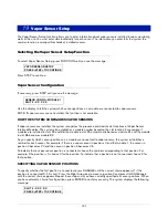
SPECIFYING VAPOR THRESHOLD LEVELS
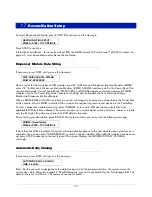
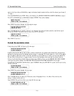
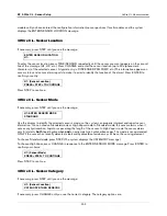
To enter the vapor threshold for the selected sensor, press CHANGE in response to the SENSOR THRESHOLD
message. Enter the vapor threshold value that you calculated based on the formula described above (between 1k
and 100k ohms). Press ENTER to confirm your entry:
Press STEP to continue.
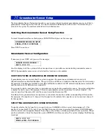
Vapor Sensor Category
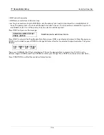
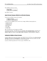
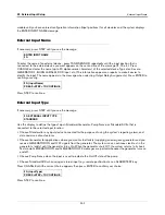
If necessary, press STEP until you see the message:
If necessary, press CHANGE until you see the correct category then press ENTER. The category options are:
•
ANNULAR SPACE
•
DISPENSER PAN
•
MONITOR WELL
•
STP SUMP
•
PIPING SUMP
When the correct category displays, press ENTER.
WARNING
This system contains electrical voltages that can be lethal.
Electrical shock resulting in serious injury or death could result if incorrect
service procedures are used.
When you perform the following procedure:
1. Read all instructions carefully.
2. Turn Off power to the console.
OFF
OFF
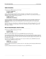
VAPOR THRESHOLD: XXXXXX
PRESS <STEP> TO CONTINUE
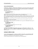
V1: (Sensor Location)
CATEGORY:OTHER SENSORS


