Setup
Introduction
This section describes how to perform PMC setup using the TLS console’s front panel buttons and display. The
procedures in this manual follow standard TLS console setup programming input, i.e., keypad/display interaction. If
necessary, refer to Section 2 of the TLS-3XX System Setup manual (P/N 576013-623) to review entering data via
the front panel keypads.
All PMC-related equipment must be installed in the site and connected to the TLS console prior to beginning the
setups covered in this section. As with all TLS connections, you cannot change sensor wiring or module slots after
programming or the console may not operate properly. Reference the section entitled “Connecting Probe/Sensor
Wiring to Consoles” in the TLS-3XX Site Prep and Installation manual (P/N 576013-879) for rewiring precautions.
Smart Sensor Setup
The Smart Sensor Interface Module is installed in the Intrinsically-Safe bay of the TLS console. This module
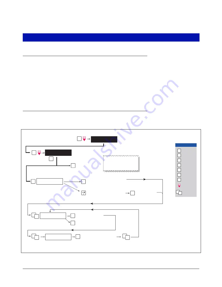
monitors the Vapor Pressure Sensor. Figure 2 diagrams the Smart Sensor setup procedure.
Figure 2. Smart Sensor Setup
SS CONFIG - MODULE 1
SLOT X - X X X X X X X X
S
isd\pmc-5.eps
ENTER SMARTSENSOR LABEL
sX:
S1: SELECT SS CATEGORY
UNKNOWN
C
C
E
S
E
S
E
S
P
F
SMARTSENSOR SETUP
PRESS <STEP> TO CONTINUE
SETUP MODE
PRESS <FUNCTION> TO CONT
M
P
C
C
C
F
P
S
T
Change
E
Enter
Function
M
Mode
Step
Tank/Sensor
Key press
sequence
Repress until
desired message
appears in display
Key Legend
1
2
Select sensor category
(e.g., Vapor Pressure Sensor)
Press this button and select type.
Note: User can only change assigment
if device has not identified itself. If
actual device disagrees with assigned
type, actual type overrides assigned
type.
The first of the installed SS modules
appears in this display. If this is not the
module to which the Vapor Pressure
Sensor (VPS) is connected, press the
Tank/Sensor button to select another
SS module.
Press once and the first position blinks. If
the VPS is connected to the first position
of the SS module, press this button again
and the X changes to a 1.
Press this button and
the X changes to the
number of the VPS
connection (2-8).
Prints out a copy of the
SmartSensor Setup.
See example at right.
Press this button and enter
a label for the sensor, e.g.,
VPS: FP1&2.
T
Press this button to
change to another sensor.
If the VPS is connected to a position other
than the first, continue to press this button
until the VPS connected position blinks.
SMARTSENSOR SETUP
----------------------
S01:VP SENSOR
CATEGORY VAPOR PRESSURE
Section 16
Pressure Management Control
16-5


