Installation Guide
Wiring the TLS RF
10
Wiring the TLS RF
WARNING
The unit contains voltages which can be lethal.
Connecting power wires to a live circuit can cause electrical shock that may result
in serious injury or death.
Turn power off at the circuit breaker before connecting wiring to the TLS RF.
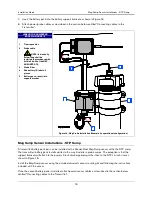
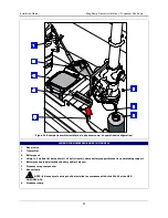
Attach conduit from the power panel to the unit’s power wiring knockouts only (1
on top and 1 on bottom, ref. Figure 3)
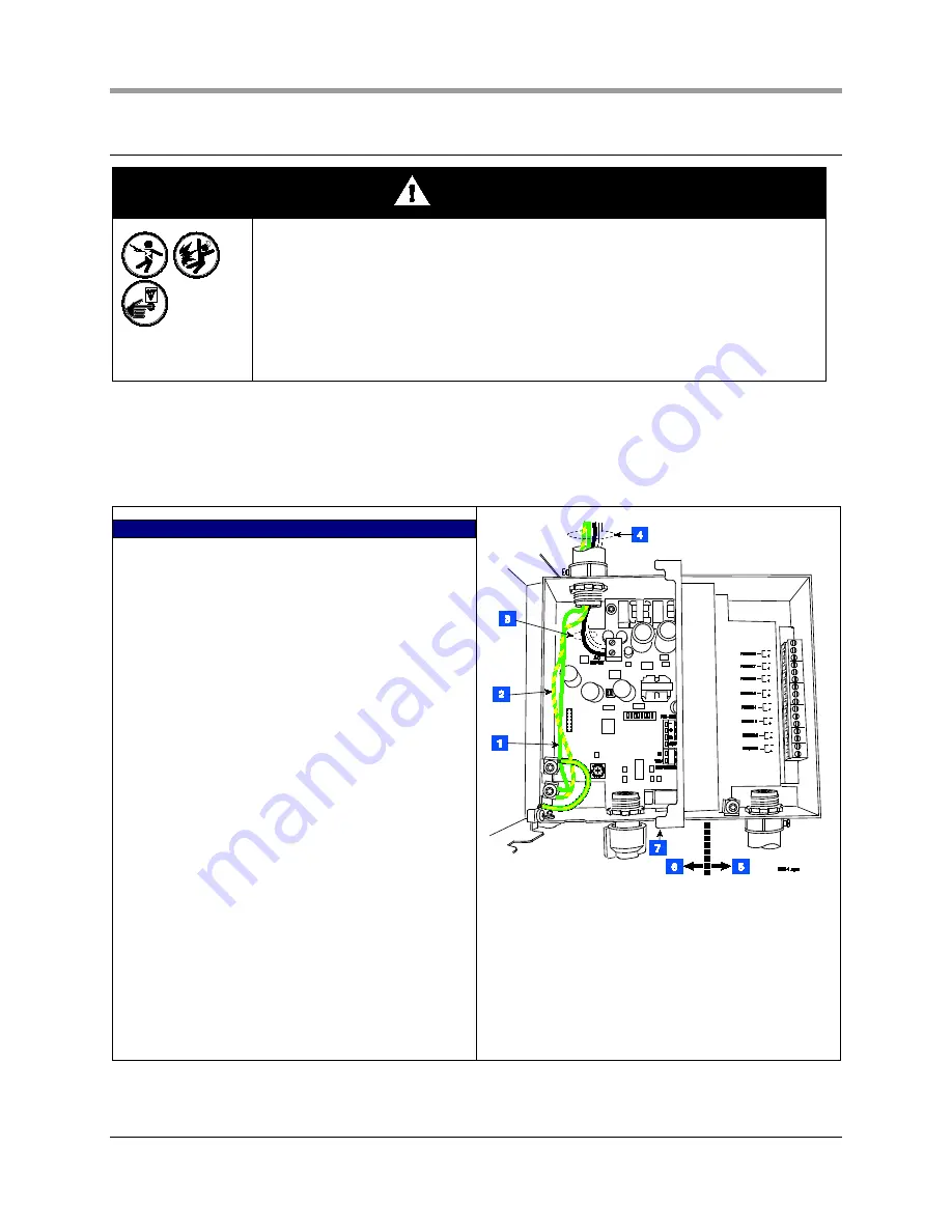
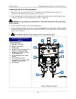
To connect power wiring see Figure 5. To connect receiver wiring see Figure 6. To daisy chain two TLS RFs,
see Figure 8 and
. To connect TLS RF data output wiring to the TLS console see Figure 10.
LEGEND FOR NUMBERED BOXES IN FIGURE 5
1.
Attach chassis ground wire (#14 AWG) to ground lug.
2.
Protective earthing conductor (green and yellow).
Attach #12AWG barrier ground wire to ground lug.
Ground must be the same as the supply and less
than 1.0 ohms to ground.
3.
AC power input wires (#14 AWG) to AC INPUT
terminals.
4.
POWER WIRING NOTES:
- Barrier ground must be #12 AWG or larger
diameter.
- Check to be sure that the electrical resistance -
between the unit ground lug and a known good earth
ground is less than 1 ohm.
- Connect the power supply wires in the power panel
to a separate dedicated circuit.
- Electrical rating power input - 120 Vac or 240 Vac,
50/60 Hz, 2 A max.
- See Figure 3 for actual locations of power conduit
knockouts into the unit. Power wiring must enter
only in one of these knockouts.
5.
Intrinsically-safe side
6.
Power side
7.
RS-232 diagnostic port:
- Baud rate - 9600
- Data length - 8
- Parity - None
- Stop bits - 1
Figure 5. Wiring AC power to the TLS RF


