Installation Guide
Wiring the TLS RF
13
terminals in both TLS RFs.
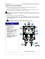
LEGEND FOR NUMBERED BOXES
IN FIGURE 10
Note: Output wiring from the TLS
RF to the TLS console is an
intrinsically safe circuit.
NOTE: Intrinsically safe
wiring shall be installed in
accordance with Article 504-20 of
the NEC, ANSI/NFPA 70.
1.
Received transmitter data
output terminals (1-8).
2.
In this example, device output
1 is a Mag probe - Observe
polarity. Note: each time a
transmission is received from
this device, LED 1 (see item 5
in Figure 11) will flash.
3.
In this example, device output
2 is a Mag Sump Sensor -
Observe polarity. Note: each
time a transmission is received
from this device, LED 2 (see
item 5 in Figure 11) will flash.
4.
1/2” i.p.s. conduit to TLS
console
5.
Probe interface module in TLS
console.
6.
SmartSensor interface module
in TLS console
7.
Intrinsically-safe side
8.
Power side
Figure 10. Wiring Data Outputs from TLS RF to TLS Console
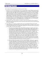
Figure 11 locates the diagnostic lights and setup switches in the TLS RF.
Each TLS RF in the site network must have a unique device set number (0 or 1). The factory default setting is
‘0’. You must select ‘0’ for the master TLS RF unit. The site’s Receiver must also be connected to the master
TLS RF.
If a second TLS RF is required, enter ‘1’ in the auxiliary TLS RF.


