Installation Guide
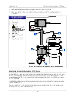
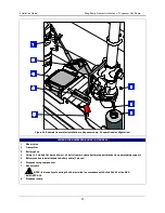
Mag Sump Sensor Installations - Dispenser Pan Sump
22
CONNECTING CABLES TO THE TRANSMITTER
1.
Remove the cover of the transmitter and set it aside Make sure the battery/dc power cable is not
connected to the battery pack or dc power source at this time.
2.
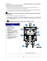
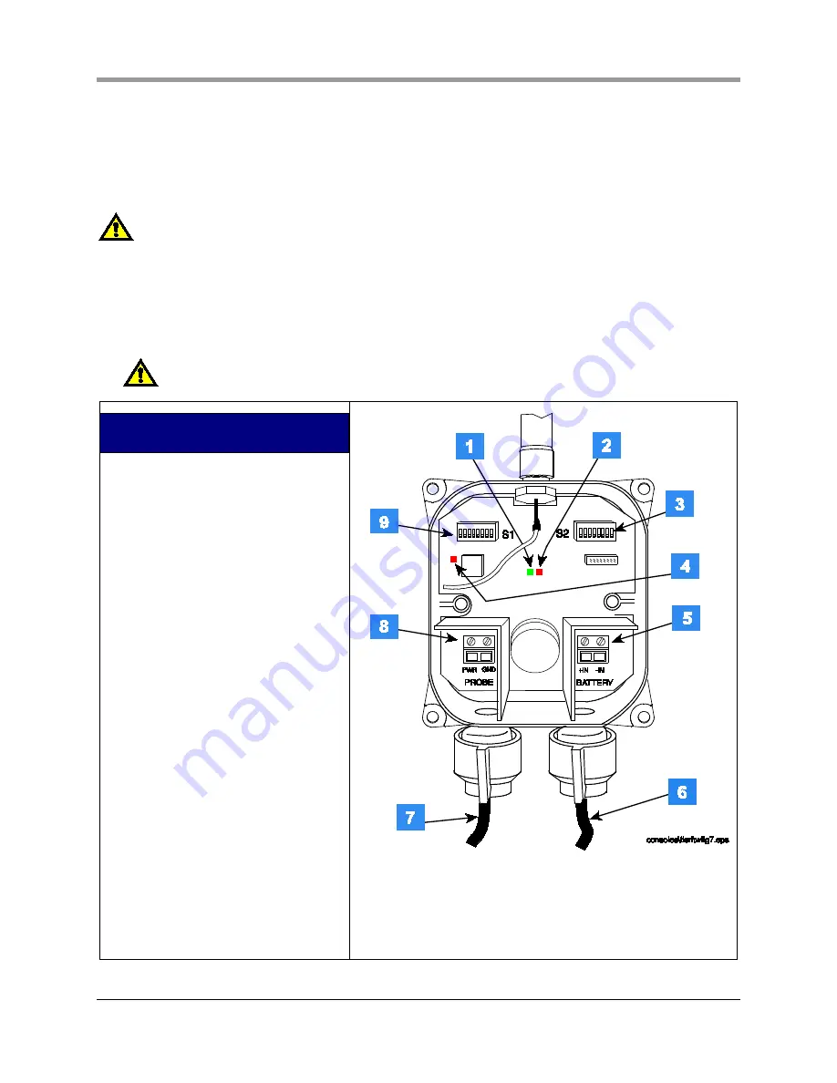
Push the probe/sensor cable through the left cord grip bushing and the battery cable through the right
cord grip (see Figure 21). Strip the cable leads as shown in Figure 22.
WARNING! To prevent ignition of flammable or combustible atmosphere disconnect power
before servicing.
3.
Set S1 and S2 DIP switches as desired (ref. Appendix C).
4.
Connect the Mag probe/Mag Sump sensor cable to the PROBE terminal block (white to PWR and black
to GND) and the battery pack/dc power cable to the BATTERY terminal block (white to +IN and black to -
IN) as shown in Figure 21.
5.
Hand tighten both cable entry cord grip nuts to prevent water entry!
LEGEND FOR NUMBERED BOXES IN
TRANSMITTER WIRING
1.
Green LED – Unit status.
2.
Red LED – Radio status.
3.
S2 DIP switch
4.
Red LED – Flashes only when radio is
powered on in Diagnostic Mode.
5.
Battery power in terminals (+IN and –
IN). Observe polarity!
6.
Cable from battery pack – observe
polarity!
7.
Cable from probe or sensor
8.
Probe/sensor input terminals (PWR
and GND) - observe polarity!
9.
S1 DIP switch
Figure 21. Wiring the Transmitter


