Installation Guide
Receiver Installation
23
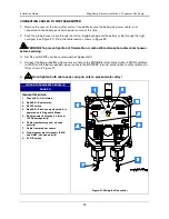
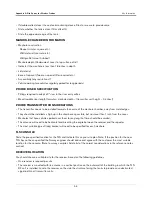
Figure 22. Connecting wiring to transmitter terminal blocks.
LEGEND FOR NUMBERED BOXES IN FIGURE 22
1.
Strip back cable and wire jackets the amount shown.
2.
Use a screwdriver with the proper blade width
3.
Insert the probe cable ends through the housing and into the proper lower openings in the terminal block as you
tighten down the retaining screws.
Both wires must be tight in terminals!
6.
To assure a water-tight seal between the cover and the enclosure, follow these steps:
a. Insert the four cover screws through the cover and then press on the retaining washers to hold the
screws in place.
b. Make sure that the cover gasket is free of dirt and debris on both sides of the gasket and that the inside
of the cover is clean in the gasket area.
c. Position the gasket into the cover groove, assuring that it is pressed fully into the groove and sitting
completely flat.
d. Assemble the cover onto the enclosure, tightening the screws in a couple of turns each. Using an
alternating ‘X’ pattern, continue to tighten the screws until they are all tight.
7.
Attach the red battery ID labels from the installation kit to the battery cable at both ends as shown in
8.
Refer to the Site Startup Procedure before attaching battery cable to battery pack connector.
Receiver Installation
1.
One receiver is required per site and it is mounted in the vertical position (antenna up) on the outer wall of
the same building housing the TLS RF. The receiver is attached to its mounting bracket with #10 x 1/2”
taptite screws from its install kit (see Figure 23). The L-bracket is then mounted on the outer wall of the
building using appropriate fasteners (customer supplied). NOTE: Locate the receiver on the side of the
building facing the tanks to provide an unobstructed signal path. When locating the mounting position,
keep in mind that the RS-485 cable connecting the receiver to the TLS RF must be less than 250 feet in
length. Avoid placing the receiver near motors (e.g., power roof vents), fluorescent lighting (min. 1 foot
separation), pumps, welders.
2.
Run the RS-485 cable (Belden #3107A or equiv.) from the TLS RF through the building’s wall to the
receiver. Caulk the cable where it passes through wall openings. Use cable clamps at appropriate
intervals to secure the cable to the walls.


