background image

Introduction

Safety Warnings

3

Safety Warnings

To protect yourself and your equipment, observe the following warnings and important information:
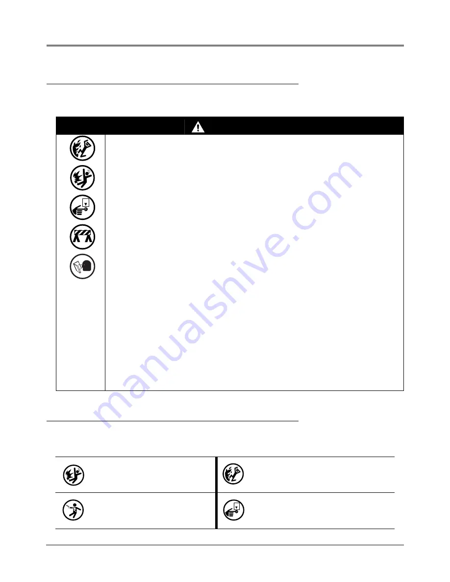
Safety Symbols

The following safety symbols may be used throughout this manual to alert you to important safety hazards and 
precautions

WARNING

This product is to be installed and operated in the highly combustible environment of a 
gasoline storage tank where flammable liquids and explosive vapors may be present. 

FAILURE TO COMPLY WITH THE FOLLOWING WARNINGS AND SAFETY PRECAUTIONS 
COULD CAUSE DAMAGE TO PROPERTY, ENVIRONMENT, RESULTING IN SERIOUS 
INJURY OR DEATH.

1. Read and follow all instructions in this manual, including all safety warnings to 

protect yourself and others from serious injury, explosion, or electrical shock.

2. Comply with all applicable codes including: the National Electrical Code; federal, 

state, and local codes; and other applicable safety codes. 

3. To protect yourself and others from being struck by vehicles, block off your work area 

during installation or service.

4. Do not alter or modify any component or substitute components in this kit. 

5. Warning! Substitution of components may impair intrinsic safety.

6. Field wiring to the Sensor must not share a conduit with any non-intrinsically safe 

device’s wiring.

7. Warning! To prevent ignition of flammable or combustible atmospheres, disconnect 

power before servicing.

8. Before installing or taking the unit into a hazardous area, earth the unit in a safe area 

to remove any static charge. Then immediately transport the unit to the installation 
site. Do not rub or clean the unit prior to installation. Cleaning is not required under 
normal service conditions. Do not rub or clean the unit after installation. If the unit is 
not fixed to a known earth point when installed, ensure that a separate earth 
connection is made to prevent the potential of a static discharge. When fitting or 
removing the unit, use of anti-static footwear or clothing is required.

9. Materials used in the construction of this device do not contain, by mass, more than 

10% in total of aluminum, magnesium, zirconium and titanium or 7.5% in total of 
magnesium, titanium and zirconium.

10. A groundwater sensor should be installed only in wet wells where preliminary testing 

has determined that water in the well is not contaminated, or contaminated water has 
been remediated and is now clean.

EXPLOSIVE

Fuels and their vapors are extremely explosive 
if ignited.

FLAMMABLE

Fuels and their vapors are extremely flammable.

ELECTRICITY

High voltage exists in, and is supplied to, the 
device. A potential shock hazard exists.

TURN POWER OFF

Live power to a device creates a potential shock haz-
ard. Turn Off power to the device and associated 
accessories when servicing the unit.

OFF

OFF

Summary of Contents for TLS-450/8600

Page 1: ...Manual No 576013 763 Revision K Installation Guide Groundwater Sensor ...

Page 2: ...ur Terms and Conditions VEEDER ROOT S PREFERRED CARRIER 1 Contact Veeder Root Customer Service at 800 873 3313 with the specific part numbers and quantities that were missing or received damaged 2 Fax signed Bill of Lading BOL to Veeder Root Customer Service at 800 234 5350 3 Veeder Root will file the claim with the carrier and replace the damaged missing product at no charge to the customer Custo...

Page 3: ...ments 1 Product Marking Information 1 Related Documents 1 Safety Warnings 3 Safety Symbols 3 Installation Components 4 Sensor Installation 5 Figures Figure 1 Installation Kit 4 Figure 2 Groundwater Sensor Installation 5 Figure 3 Epoxy Sealing Field Wiring Connections 6 ...

Page 4: ...all Veeder Root Series Tank Monitoring Systems including Line Leak Detection In addition Contractors with the following sub certification designations are approved to perform installation checkout startup programming system tests troubleshooting service techniques and operations training on the designated system Wireless 2 Tall Tank Warranty Registrations may only be submitted by selected Distribu...

Page 5: ... Sensor Connections I S I S I S I S Weatherproof Junction Box I S Sensor Connections Non Hazardous Location Associated Apparatus 8470 TLS 350 8482 TLS 350R ATG Console Non Hazardous Location Associated Apparatus 8600 TLS 450 ATG Console TLS XB 8603 Non Hazardous Location Associated Apparatus 8601 TLS4 Console 1 2 1 2 OR F F G G W W F G W I S CIRCUIT FOR HAZLOC SENSOR F N 794380 XXX S N XXXXXX 40 C...

Page 6: ...g 7 Warning To prevent ignition of flammable or combustible atmospheres disconnect power before servicing 8 Before installing or taking the unit into a hazardous area earth the unit in a safe area to remove any static charge Then immediately transport the unit to the installation site Do not rub or clean the unit prior to installation Cleaning is not required under normal service conditions Do not...

Page 7: ...sure in the lines can cause serious eye injuries Always wear eye protection INJURY Careless or improper handling of materials can result in bodily injury READ ALL RELATED MANUALS Knowledge of all related procedures before you begin work is important Read and under stand all manuals thoroughly If you do not understand a procedure ask someone who does Wire nut 3 Tie wrap 1 Epoxy sealant 1 P N 331028...

Page 8: ... mark the sensor with a piece of tape at the point even with the top of the well casing 5 Secure the sensor at the point marked with the tape to the retainer under the sensor well cap Allow any excess sensor length should be no more than 2 feet to hang loosely from the retainer Figure 2 Figure 2 Groundwater Sensor Installation OFF Well Cover Retainer Extra Sensor Length Should Not Exceed 2 Feet Se...

Page 9: ...nsor cap to ensure that the locking handle cannot be opened by unauthorized personnel Figure 3 Epoxy Sealing Field Wiring Connections consoles epxy3w eps To console To sensor Tie wrap Wire nuts A C B Make sure that the ends of cable sheathing are sub merged in sealant Instructions NOTE When temperature is below 50 F 10 C keep resin in a warm place prior to mixing e g in an inside pocket next to bo...

Page 10: ...For technical support sales or other assistance please visit www veeder com ...

Reviews: