background image

7


 Preparing The TLS-450 Console For Upgrade

Removing The Display Door

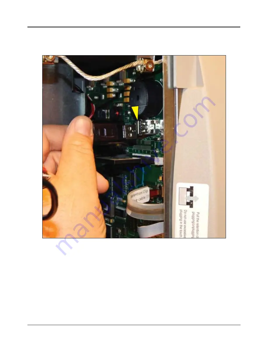
3. If a printer is installed, unplug the printer USB cable from the CPU board connector (see Figure 6).

Figure 6.   Removing Optional Printer Cable

4. Unplug the Display panel’s Touchscreen control cable (3) Data cable (4), and LED backlight cable (5) 

connectors from the CPU board (see Figure 7).

Summary of Contents for TLS-450

Page 1: ...Manual No 577014 048 Revision C Upgrade Instructions TLS 450 To TLS 450PLUS Console...

Page 2: ...ur Terms and Conditions VEEDER ROOT S PREFERRED CARRIER 1 Contact Veeder Root Customer Service at 800 873 3313 with the specific part numbers and quantities that were missing or received damaged 2 Fax...

Page 3: ...ptional Printer Cable 7 Figure 7 Removing The Three Display Panel Cables 8 Figure 8 Disconnect The Ground Wire From The Display Door 9 Figure 8 Locating CPU Board Retention Snap Pins 10 Figure 9 Locat...

Page 4: ...checkout startup programming system tests troubleshooting service techniques and operations training on the designated system Wireless 2 Tall Tank Warranty Registrations may only be submitted by selec...

Page 5: ...that must be kept intrinsically safe FAILURE TO COMPLY WITH THE FOLLOWING WARNINGS AND SAFETY PRECAUTIONS COULD CAUSE DAMAGE TO PROPERTY ENVIRONMENT RESULTING IN SERIOUS INJURY OR DEATH 1 Turn off an...

Page 6: ...c wrist strap Part No 576010 908 included in your component replacement kit 6 Never slide parts over any surface 7 Avoid plastic vinyl and Styrofoam in your work area Before Turning Off Power Before p...

Page 7: ...on on the Diagnostic Maintenance screen see Figure 3 to open the Software Maintenance Backup Restore tab screen see Figure 4 Figure 3 Software Maintenance Button LEGEND FOR NUMBERED BOX IN Figure 2 1...

Page 8: ...isplays you can safely remove the V R Backup Thumbdrive 6 Print out or write down TLS 450 Ethernet settings 7 Print out or write down all remaining TLS 450 communication port settings LEGEND FOR NUMBE...

Page 9: ...left see Figure 5 Figure 5 Opening The TLS 450 Console Doors LEGEND FOR NUMBERED BOXES IN Figure 5 1 Left Printer door 2 Using a T 15 Torx driver remove the top and bottom screws securing left door an...

Page 10: ...a printer is installed unplug the printer USB cable from the CPU board connector see Figure 6 Figure 6 Removing Optional Printer Cable 4 Unplug the Display panel s Touchscreen control cable 3 Data ca...

Page 11: ...Figure 7 Removing The Three Display Panel Cables LEGEND FOR NUMBERED BOXES IN Figure 7 1 Top Display door hinge shoulder screw 2 Grounding wire 3 Touchscreen control cable 4 Display data cable 5 LED...

Page 12: ...und wire from the Display door at the grounding clamp Figure 8 Disconnect The Ground Wire From The Display Door 6 Remove the top and bottom Display door hinge shoulder screws and remove the door items...

Page 13: ...er beneath one of the pins and press up releasing the CPU board from the snap pin see item 4 in Figure 8 Repeat at each of the remaining two retention pins LEGEND FOR NUMBERED BOXES IN Figure 8 1 Boar...

Page 14: ...C34 C34 J_USB1 J_USB1 R16 R16 R17 R17 1 1 L5 L5 A A 25 25 Secondary C308 C308 15 15 20 20 45 45 40 40 45 45 J6 J6 25 25 Primary Q2 Q2 50 50 C103 C103 C249 C249 U24 U24 Console Port Console Port C57 C5...

Page 15: ...ving Comm Module Clamp 2 Remove Comm boards from Comm Module Bay slots 4 and 5 see Figure 1 and set aside 3 Install the TLS 450PLUS Ethernet Interface module in slot 4 see Figure 11 Figure 11 Install...

Page 16: ...ee Figure 12 Figure 12 Install USB Wireless Module In Slot 5 5 Relocate other Comm module s in available slot s If CDIM module was in slot 4 relocate it to slot 1 or 2 Replace Comm module clamp and se...

Page 17: ...cing up in its socket see Figure 15 Figure 14 Insert iButton In Socket On New TLS 450PLUS CPU Board Figure 15 Install iButton Flange Facing Up 2 Install the new TLS 450PLUS CPU board into the console...

Page 18: ...ors Blue cable E 3 to top connector yellow E 2 to next down and red E 1 to lower connector see Figure 17 Figure 17 Connect Ethernet Cables 5 Connect the Wireless cable to the CPU board see Figure 18 F...

Page 19: ...cable to the CPU board s USB 1 top connector see Figure 20 Figure 20 Connect Optional Printer USB Cable Installing New TLS 450PLUS Display Door 1 Install the new TLS 450PLUS Display door on the consol...

Page 20: ...TLS 450 Console For Upgrade Installing New TLS 450PLUS Display Door Figure 21 Install The New TLS 450PLUS Display Door 2 Connect the Ground cable to the Display door see Figure 22 Figure 22 Connect T...

Page 21: ...the flap 1a until it rests against the connector Verify the Display Data ribbon cable is securely seated in the connector and that the flap is down against the connector as shown in the enlarged secti...

Page 22: ...that the read write protect switch on the side of the card is in the position shown in item 1 Figure 25 Insert the SD card into its enclosure with the contact side facing the CPU board item 2 and gent...

Page 23: ...appear before the Discover Mode is complete however the console may still be in the process of connecting to all of its monitored devices Waiting 5 minutes ensures all devices have been recognized by...

Page 24: ...For technical support sales or other assistance please visit www veeder com...

Reviews: