7
Replacing The CPU Board
Before Turning Off Power
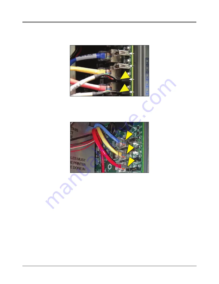
8. Remove the two USB module cables from the CPU board USB connectors USB3 and USB4 (see Figure 8).
Figure 8. Remove USB Module Cables From CPU Board
9. Remove the three Ethernet Module cables ENET2 (blue), ENET1 (yellow) and ENET0 (red) from the CPU
board (see Figure 9).
Figure 9. Remove Ethernet Module Cables From CPU Board
10.Locate the three retention snap pins along the front edge of the CPU board. Position your forefinger beneath
one of the pins and press up releasing the CPU board from the snap pin. Repeat at each of the remaining two
retention pins.
11.Tilt the board a little away from the bulkhead and grasping the edge of the board pull out firmly to remove the
board from its backplane board connector. Once the CPU board is free from the connector, slowly remove the
board from the console.
12.With anti-static strap attached to wrist and to a grounded metal surface, place the CPU board on a clean work
surface.
13.Locate the SD card on the CPU board (see Figure 10). If a SD card is not installed as shown, skip Step 14
and go to Step 15.
USB1
USB2
USB3
USB4
USB1
USB2
USB3
USB4
E2
E1
E0


