5
Replacing The CPU Board
Before Turning Off Power
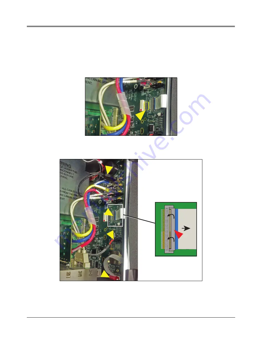
2. For right doors with an Acknowledge Switch panel, remove its cable from its connector (J502) on the CPU
board (see Figure 4).
For right doors with the optional touch display, remove the Display Data cable (pointer 1 in Figure 5) from the
CPU board connector. Rotate the locking member of the cable’s Display connector (1a pointer) up 90° from
the connector’s fixed base and slide cable end out
Figure 4. Remove the Acknowledge Switch Panel Cable From Its CPU Board Connector
Figure 5. Remove Optional Printer And Display Cables From CPU Board
3. Remove the LED Back light cable (pointer 2 in Figure 5) from the CPU board connector.
1
4
2
3
1a


