19
Probe Installation
Probe Wiring Precautions
Probe Wiring Precautions
To The Installer! You Must Read And Understand This Information.
INPUT/OUTPUT WIRING POSITIONS AND LABELING
In all cases, the devices wired to the console’s input/output terminal blocks must be recorded to prevent improper
replacement during installation or service.
A circuit directory is listed below for this purpose.
During programming, the probes wired to each position are identified and stored in memory. If a probe is removed and
reconnected to a different set of input terminals after programming, the system will not properly recognize the data being
received.
Wiring Assignments
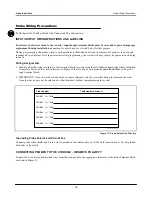
1. Identify all probe wires according to their terminal block location using the self-adhesive numbering labels furnished.
Accurately record on the circuit directory in Figure 13 the location of each probe
as you attach wires
to the probe
input terminal block.
2. IMPORTANT! Once a device has been wired to certain terminals and the system has been programmed, the wires
from that device may not be relocated to other terminals without reprogramming the system
Figure 13. Probe Installation Directory
Grounding Probe Shields and Drain Wires
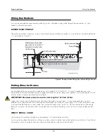
Connect probe cable shields and drain wires to ground in the console only, not at the field junction boxes. Do not ground
both ends of the shield.
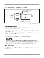
CONNECTING PROBES TO THE CONSOLE - OBSERVE POLARITY
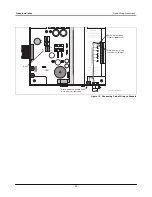
Connect the two color-coded/marked wires from the each probe to the appropriate terminals of the Probe Terminal Block
as shown in Figure 14.
PROBE 1 IN
TANK Number & Product
Probe Number
TANK
PROBE 2 IN TANK
PROBE 3 IN TANK
PROBE 4 IN TANK
PROBE 5 IN TANK
PROBE 6 IN TANK
consoles\tls50\prbtnk.eps


