4
Component Identification
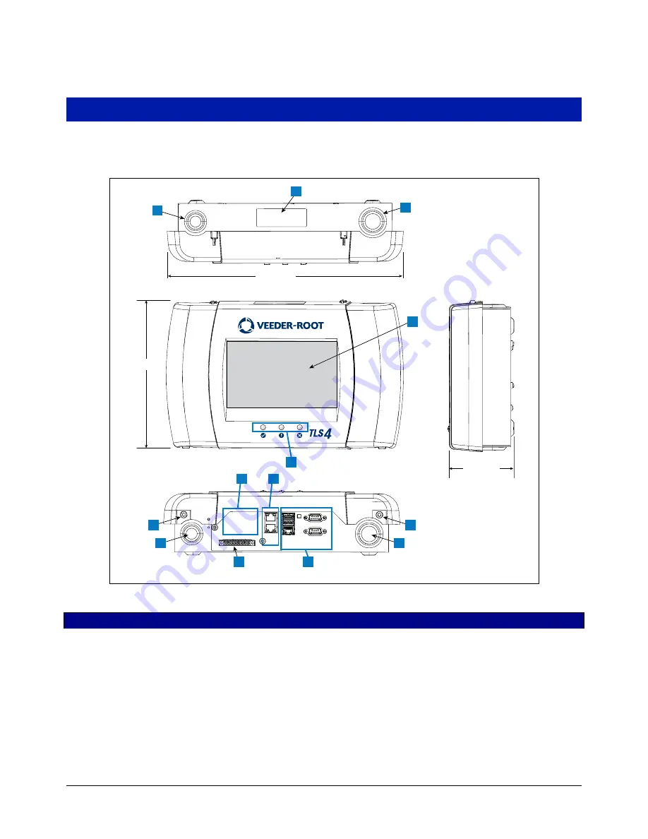
Figure 1 through Figure 4 show assembly and component locations referenced in this manual.
Figure 1. TLS4/8601 Series Console - Dimensions
LEGEND FOR NUMBERED BOXES IN Figure 1
1. Power conduit knockout (1 top/1 bottom)
2. Console label contains input power ratings and Form and Serial
number
3. Intrinsically safe wiring conduit knockout (1 top/1 bottom)
4. Optional touch screen display
5. Status LEDs
6. T15 screws secure cover (2 places)
7. Communication ports - standard:
Serial ports 1 (full handshaking) and 2
USB ports 1 and 2
Ethernet port 1
8. Communication port - optional integrated ethernet switch ports 2
and 3
9. Factory Installed Optional Module
10. Expansion port
8
” (204mm)
3.5” (89mm)
13” (331mm)
1
6
6
1
3
3
ETH 2
ETH
3
U
S
B 1
U
S
B 2
ETH 1
S
ERIAL 1
S
ERIAL 2
EXPAN
S
ION
2
7
9
10
5
4
1
10
8


