Component Identification
TLS4/8601 Kits
5
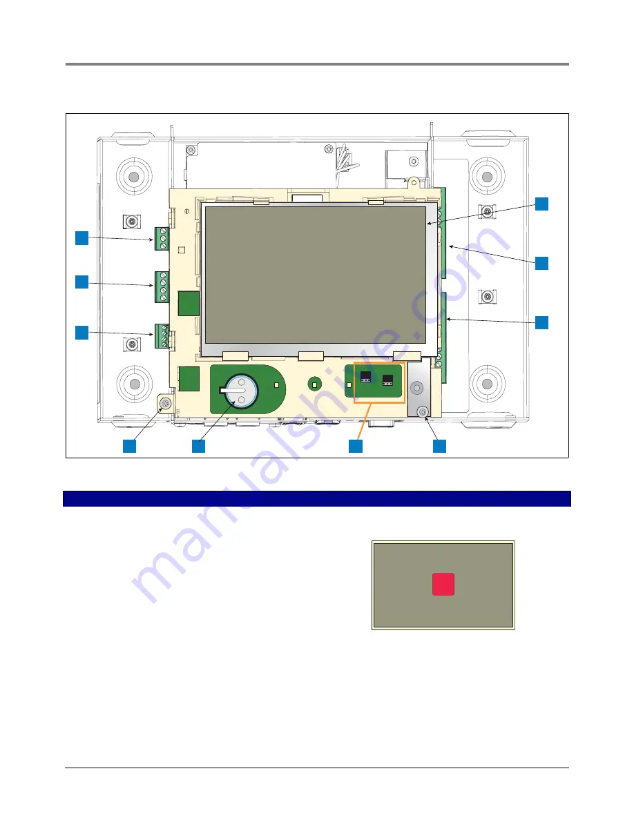
Figure 2. Component Locations (Front Cover Removed)
LEGEND FOR NUMBERED BOXES IN Figure 2
1. AC or DC input power connector (as ordered)
2. High voltage output relay connector
3. Low voltage external input connector
4. T15 screw secures Display/CPU assembly
5. Rechargeable 3V Lithium battery (battery backup)
6. RS232/485 selection jumpers SERIAL 1 (P1) and SERIAL 2
(P2)(factory set to RS232 position)
7. T20 screw secures Display/CPU assembly
8. Optional 6-device intrinsically safe input connector (7 - 12)
9. Standard 6-device intrinsically safe input connector (1 - 6)
10. Optional Graphical User Interface (GUI) display (on non-display
consoles, the GUI display is replaced with the Alarm Reset (Ack)
button panel shown belowl)
5
3
1
2
4
6
7
8
P2 RS485
J39
J38
P2 RS232
P1 RS485
P1 RS232
9
+
+
10
ALARM
RE
S
ET


