background image

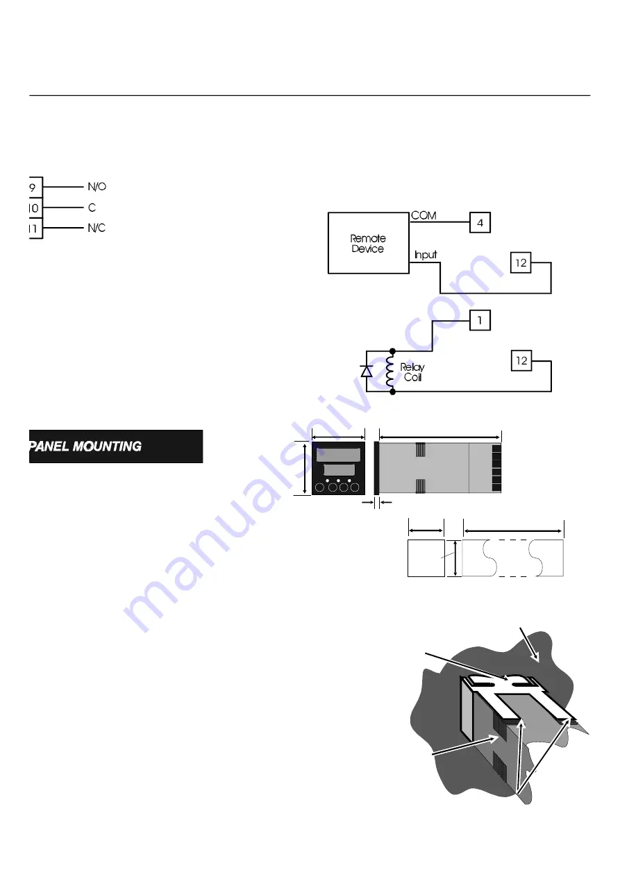
Open Collector Output

Connect Terminals 12 (open collector) and 4 (COM) to solid state

devices as shown below (upper circuit). To drive DC relay coils,

connect Terminal 12 and V+ (Terminal 1) as shown on below (lower 

circuit). Suppress switching transients with a suppression diode,

connected as shown.

48m

48m

10mm (approx.)

110

45m

45m

(48n - 4)mm

Single

Installatio

Multiple Installation (n 

Counters)

Panel Mounting

Make cut-out(s) according to the details in

the diagram on the right. The maximum

panel thickness is 6 mm.

Rear face of mounting panel

Mounting bracket

Counter
housing

Tongues on mounting bracket
engage in ratchet slots on Counter housing

Insert the rear of the Counter housing

through the cut-out (from the front of the

mounting panel) and hold the Counter

lightly in position against the panel. Ensure

that the panel gasket is not distorted and that 

the Controller is positioned squarely against

the mounting panel. 

Apply pressure to the

front panel bezel only.

 Slide the mounting

bracket in place (see right) and push it

forward until it is firmly in contact with the

rear face of the mounting panel (tongues on

the bracket should engage in matching

rachet positions on the Counter housing and

the mounting bracket springs should push

firmly against the mounting panel rear face).

CAUTION

Do not remove the panel
gasket from the Counter as
this may result in
inadequate clamping of the
Counter in the mounting
panel.

I N S T A L L A T I O N

Relay Output

Connect AC or DC load circuits to Terminals 9, 10 & 11

(see below) as required. Do not route load wiring near

count input or transistor output signals.

Summary of Contents for V454501

Page 1: ...e V454500 family of preset counters combines state of the art circuitry and electronic assembly techniques with an ergonomic package design that results in the most cost effective high performance cou...

Page 2: ...s display of Count and Preset data Red LED display Annunciators show input display and output status Ergonomic Keypad Simple key sequences to view and edit Presets Front Panel Reset key can be disable...

Page 3: ...Current Sinking NPN Count Inputs Connect Add count input to Terminal 2 A and or Subtract count input to Terminal 3 B see below In Configuration Mode set PuLL parameter to YES and for Add Subtract oper...

Page 4: ...rom the front of the mounting panel and hold the Counter lightly in position against the panel Ensure that the panel gasket is not distorted and that the Controller is positioned squarely against the...

Page 5: ...ting left most digit will start to flash and to move between the digits Once the proper digit is selected flashing with the Next key its value can be altered through use of the Down key Program Mode U...

Page 6: ...ts are as required press the ENT key to confirm the changes the display will stop flashing IMPORTANT You must press the ENT key within 15 seconds of the last keypress when entering a new value otherwi...

Page 7: ...e digits will flash use Next key to select each digit to be adjusted and adjust digit value using Down key When adjustment is complete press ENT key to exit Edit Mode digits will become static 2 To ad...

Page 8: ...a parameter use the Down key to step through the parameters when the desired parameter description is shown in the upper display press the Next key to enter Edit Mode and to scroll through the availab...

Page 9: ...medium speed 25 0ms low speed Control Inputs Remote Reset Terminal 5 edge sensitive Program Mode Terminal 6 level sensitive Input Voltage High 3 0V or open Low 2 0V Input Impedance 4 7k to V Input Re...

Page 10: ...10 N O T E S...

Page 11: ...11 N O T E S...

Page 12: ...Neuhausen ADF Tel 49 71589003 0 Fax 49 71589003 32 In Brazil Veeder Root do Brasil Rua Ado Benatti No 92 Caixa Postal 8343 CEP 05037 010 S o Paulo Tel 55 118612155 Fax 55 118611982 1675 N Delany Road...

Reviews: