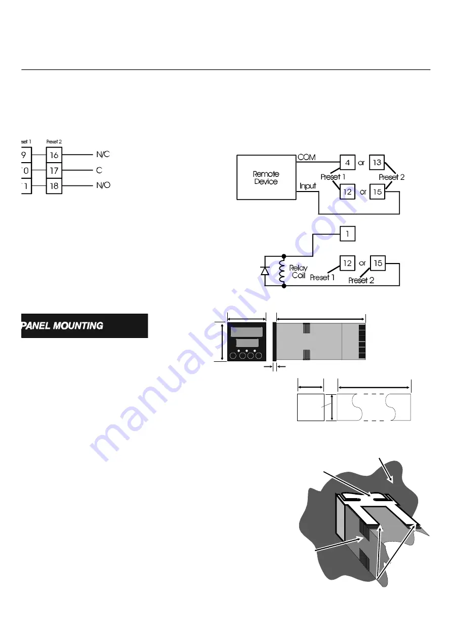
Open Collector Output
Connect Terminals 12 (Preset 1 open collector) and 4 (COM) or 15
(Preset 2 Open Collector) and 13 (COM) to solid state devices as
below (upper circuit). To drive DC relay coils, connect Terminal 12
or 15 and V+ (Terminal 1) as below (lower circuit). Suppress
switching transients with a suppression diode, connected as shown.
48m
48m
10mm (approx.)
110
45m
45m
(48n - 4)mm
Single
Installatio
Multiple Installation (n
Counters)
Panel Mounting
Make cut-out(s) according to the details in
the diagram on the right. The maximum
panel thickness is 6 mm.
Rear face of mounting panel
Mounting bracket
Counter
housing
Tongues on mounting bracket
engage in ratchet slots on Counter housing
Insert the rear of the Counter housing
through the cut-out (from the front of the
mounting panel) and hold the Counter
lightly in position against the panel. Ensure
that the panel gasket is not distorted and that
the Controller is positioned squarely against
the mounting panel.
Apply pressure to the
front panel bezel only.
Slide the mounting
bracket in place (see right) and push it
forward until it is firmly in contact with the
rear face of the mounting panel (tongues on
the bracket should engage in matching
rachet positions on the Counter housing and
the mounting bracket springs should push
firmly against the mounting panel rear face).
CAUTION
Do not remove the panel
gasket from the Counter as
this may result in
inadequate clamping of the
Counter in the mounting
panel.
I N S T A L L A T I O N
Relay Output
Connect AC or DC load circuits to Terminals 9, 10 & 11
(Preset 1) or 16,17 & 18 (Preset 2) (see below) as required.
Do not route load wiring near count input or transistor output
signals.
Summary of Contents for V454502
Page 10: ...10 N O T E S ...
Page 11: ...11 N O T E S ...


