4 FEATURES AND FUNCTIONS
4.1 Buttons
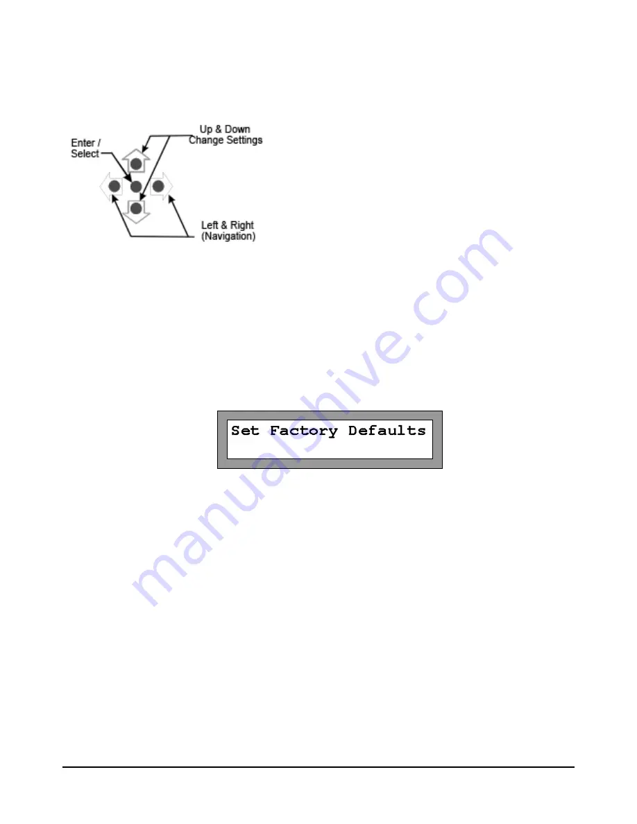
The AT1700 has a group of five buttons for manual control and to control the configuration of the AT1700 multi
-
plexer.
Left & Right Arrows are for navigation and sequence from screen to screen. Up and Down arrows increment or
decrement the current selected setting. The Center button selects the highlighted item and is used to terminate
changes (Enter).
4.2 Reset
The AT1700 may be returned to the original factory default setting by using the Left or Right arrows to scroll the
display to the “Set Factory Defaults” screen and pressing the center Enter button. This resets all parameters to
the Factory Default setting. Complete configuration is required following this step.
4.3 Test Points
A -20 dB Test Point (female “F” connector) is provided for each Output Port and is located on the front panel for
easy access.
4.4 RF Inputs and Outputs
Sixteen 1 GHz bandwidth RF inputs are provided. The AT1702 has 2 RF outputs, one for each of the internal 16-
to-1 multiplexers. As a result each output can be independently connected to any one of the shared RF inputs,
passing that signal through to the output at unity gain.
Note: At no time should “cable powering” ( 24 to 90 VAC or VDC) be applied to any of the sig-
nal ports. Doing so may cause irreparable damage to the unit and will void the warranty.
4.5 Power In
Power In is provided for powering the unit from the AC adapter provided. No other power source should be uti
-
lized unless it is provided by VeEX. An Optional 48 V DC power adapter is available.
Page 10 of 22
AT1700 series Manual D07-00-066P Rev. A00


