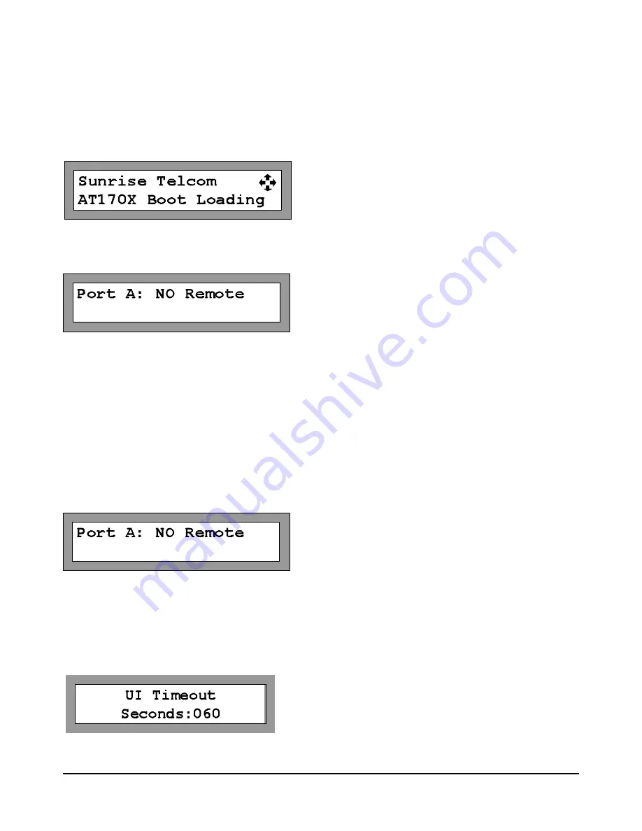
Port B: NO Remote
Port B: NO Remote
5 OPERATING MODES
5.1 Initial Operation
When the unit is powered on the firmware is loaded prior to any switch capability.
After power-up, the unit will display the current state of each multiplexer.
The AT1701 will display only Port A information (no port B). AT1702 will display both Port A and B. The mode,
Remote or Manual, is displayed along with the current input port number selected.
This condition persists until a front panel key is pressed or until a valid remote command is received on either
channel. Although displaying no selected input port the unit is in the REMOTE mode and is ready for normal
operation.
5.2 Manual Mode
When the Multiplexer is in the Manual mode, the user may scroll to the desired input Port 1 to 16 using the UP
and DOWN buttons.
The unit can be placed in manual or REMOTE mode by pressing the center ENTER button, using the left or right
arrow to navigate to the desired Port selection and pressing the Up or Down arrow to change the desired setting. .
If the AT1700 is in Manual mode the UI Timeout will begin. If a button is not pressed for the duration of the UI
timeout, the Port will automatically go back to the Remote mode following the specified delay, after the last key
press. This prevents a user from accidentally leaving the AT1700 in the manual mode and preventing a monitor
-
ing system from normal operation.
The user may set the UI Timeout delay. From the main menu, press the left or right arrow key until “UI Timeout” is
displayed. Press the center Enter key to select UI Time out. Us the left and right arrow keys to highlight the digital
to be changed. Press the Up or Down arrows to increment or decrement the desired digit. Press the center Enter
key when the desired delay is shown.
Note: The AT1700 has independent RF Input port controls for Manual and REMOTE modes to
allow switching between modes without affecting the channel selected in the other port.
Page 13 of 22
AT1700 series Manual D07-00-066P Rev. A00


