Packet Tab
678
This procedure demonstrates how to interconnect the MPA with a Fibre Channel SAN
switch.
This procedure will establish a connection that requires a Fabric and Name
Server login.
1. Verify the optical laser module being used supports the selected Fibre Channel
data rate, and the wavelength is compatible SAN equipment being tested.
2. Configure the Fibre Channel test interface.
3. Turn the TX Laser on and verify both transmit and receive optical power levels
are within specification. Then interconnect the transmit and receive test port
interfaces with the SAN equipment.
4. The test port and the SAN equipment should quickly establish a valid Link State.
The "Active" link state status can be observed under the Status section in the
Config > Set screen, and the Link State LED should be green.
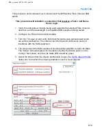
5. Select the stream from the stream profile table to open the
dialog box, from which the stream parameters need to be configured.
MPA_e_manual_D07-00-129P_RevA00
Summary of Contents for MPA
Page 2: ...MPA_e_manual_D07 00 129P_RevA00...
Page 10: ...MPA_e_manual_D07 00 129P_RevA00...
Page 82: ...MPA_e_manual_D07 00 129P_RevA00...
Page 110: ...MPA_e_manual_D07 00 129P_RevA00...
Page 134: ...MLD Tab 134 100G RS FEC Ethernet 400G RS FEC Ethernet MPA_e_manual_D07 00 129P_RevA00...
Page 255: ...Protocol Tabs 255 MPA_e_manual_D07 00 129P_RevA00...
Page 256: ...OTN Tab 256 MPA_e_manual_D07 00 129P_RevA00...
Page 748: ...MPA_e_manual_D07 00 129P_RevA00...
Page 796: ...MPA_e_manual_D07 00 129P_RevA00...


