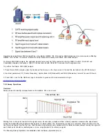
1. The "divide and conquer" method normally works best. Establish the most distant point from the headend at which the signal is
known to be good quality. Start midway between this point and the affected subscribers to locate the problem amplifier
2. Systematically check the signal level at the return path receiver test points in the headend or hub until the problem node is found
Ingress Measurement Notes:
The spectrum analyzer’s ability to measure low-level signals is limited by the noise generated inside the spectrum analyzer. The sensitivity
required to measure low-level signals is determined by the measurement setup. The spectrum analyzer
Input Attenuator
and
Resolution
Bandwidth
settings are the key factors that determine how small of a signal the spectrum analyzer can measure.
Input attenuator
- When enabled, reduces the level of the signal at the input of the mixer to avoid compression, which can produce
unwanted frequency products. An amplifier at the mixer’s output will re-amplify the attenuated signal to keep the signal peak at the same
point on the analyzer’s display. However, in addition to amplifying the attenuated input signal, the noise present in the signal and analyzer
is amplified as well. This has the undesired effect of raising the displayed noise level of the analyzer.
Resolution bandwidth
- Affects how closely a small signal can be seen in the presence of a large one. By increasing the width of this
filter, more noise energy is allowed to hit the envelope detector of the analyzer. This also has the effect of raising the displayed noise level
of the analyzer.
Maximum sensitivity
- For maximum sensitivity, both the input attenuator and resolution bandwidth settings must be minimized. If, after
adjusting the attenuation and resolution bandwidth, an ingress signal is still near the noise, stability of the displayed trace can be improved
by video filtering the display using the Video Bandwidth (VBW).
Note: Common Path Distortion (CPD)
Produced by poor contacts in the cable distribution network, these contacts create a diode or rectifier effect
which produces potentially harmful 2nd and 3rd order Intermodulation Distortion (IMD) products or beats.
These beats will occur every 6, 7 or 8MHz in the reverse path, depending on the channel plan used.
Although the magnitude of these beats is small, they increase at a node when several reverse paths are
combined.
7.5 Cable Modem
Overview:
Historically, CATV was a unidirectional medium designed to carry broadcast analog video channels to the maximum number of customers
at the lowest possible cost. The DOCSIS interface specification basically enables the deployment of data-over-cable systems on a non-
proprietary, multi-vendor, interoperable basis for transparent bidirectional transfer of Internet Protocol (IP) traffic between the cable system
head end and customer locations over an all-coaxial or Hybrid-Fiber/Coax (HFC) cable network.
In its simplest form, the system consists of a Cable Modem Termination System (CMTS) located at the headend, a coaxial or HFC
medium, and a Cable Modem (CM) located at the customer premises. In addition, DOCSIS defines physical, signalling and protocol layers
to support interoperability and evolutionary feature capabilities to permit future value-added services.
The DOCSIS layers are briefly outlined as follows:
IP network layer
Data link layer comprising:
Logical Link Control (LLC) sublayer conforming to Ethernet standards
Link security sublayer for basic privacy, authorization, and authentication
Media Access Control (MAC) sublayer for operation supporting variable-length Protocol Data Units (PDU)
Physical (PHY) layer comprising:
Downstream convergence layer conforming to MPEG-2 (Recommendation H.222.0)
Physical Media Dependent (PMD) sublayer for:
Downstream based on ITU-T Rec J.83 Annex B with either 64 or 256 Quadrature Amplitude Modulation (QAM),
concatenation of Reed-Solomon and Trellis Forward Error Correction (FEC), in addition to variable-depth interleaving
Upstream employing Quadrature Phase Shift Keying (QPSK), 16, 64 or 128QAM, support for multiple symbol rates,
cable modem controlled and programmable from the CMTS, frequency agility, fixed-frame and variable-length PDU
formats, Time-Division Multiple Access (TDMA), programmable Reed-Solomon FEC and preambles, and capability to
support future physical layer technologies.
Summary of Contents for VEPAL CX350S-D3.1
Page 1: ...CX350s D3 1 e Manual D07 00 102P RevA01 Page 1 of 109 ...
Page 13: ...Go back to top Go back to TOC CX350s D3 1 e Manual D07 00 102P RevA01 Page 13 of 109 ...
Page 16: ...Go back to top Go back to TOC CX350s D3 1 e Manual D07 00 102P RevA01 Page 16 of 109 ...
Page 21: ...Go back to top Go back to TOC CX350s D3 1 e Manual D07 00 102P RevA01 Page 21 of 109 ...
Page 57: ...Go back to top Go back to TOC 7 8 4 Remote Operations ...
Page 76: ...Go back to top Go back to TOC CX350s D3 1 e Manual D07 00 102P RevA01 Page 71 of 109 ...

