background image

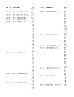
Part No. Description

Ckt

Sym

286-1766

CONN JUMPER PLUG

JP1

JP2

JP3

JP4

JP5

JP6

JP7

JP8

JP9

JP10

JP11

JP12

JP13

286-1772

CONNECTOR 36PIN STRIP TIN

JP1

JP2

JP3

JP4

JP5

JP6

JP7

JP8

JP9

JP10

JP11

JP12

JP13

286-1964

TEST POINT YELLOW .055 MNT TP1

TP2

TP3

TP4

TP5

TP6

TP7

TP8

TP9

TP10

TP11

TP12

TP13

TP14

TP15

TP16

TP17

TP18

TP19

TP20

Part No. Description

Ckt

Sym

286-2011

CONN PCB MODULAR 4PIN HS

J1

299-0303

SWITCH 6PST DIP

S1

S2

S3

S4

S5

318-0246

XFORMER 10K CT-10K CT

T1

T2

T5

T6

318-0259

XFORMER 600CT-600CT

T3

T4

T7

T8

425-0178

INT CKT NE570N

U5

U6

U8

425-0210

IC OPAMP LM348 QUAD

U1

U9

425-0488

OPAMP QUAD LMC660 OV INP

U2

U3

425-0529

IC CMOS SW DG212B 4XSPST

U4

U7

425-0530

IC LM2937 ET-10 VOLT REG

U11

534-0001

SCREW PH 4-40X1/4 NYLOK

538-0075

NUT KEP 4-40

614-0434

HEAT SINK TO-220 21C/W

13

Summary of Contents for 1505

Page 1: ...ice Manual 098 0355 CH 1 CH 1 Tx Rx MIC SPEAKER CH 2 CH 2 CH 3 CH 3 CH 4 CH 4 LEVEL ADJUST CH 1 CH 1 CH 1 MUTE Tx Rx HANDSET MIC SPEAKER CH 2 CH 2 CH 2 CH 3 CH 3 CH 3 CH 4 CH 4 CH 4 SPKR PTT 1505 MIXE...

Page 2: ...milar types of equipment should attempt to install the 1505 Only basic hand tools are re quired to remove the card change jumper set tings connect phone signal and power lines Read this section thorou...

Page 3: ...opriate service loop on in terconnecting cables 3 4 Access for Installation Servicing When installing into a Tellabs Type 10 or equivalent open frame rack ensure the front and rear of the rack have cl...

Page 4: ...e B position out by passes Rx Ch 1 s Compressor Limiter Refer to Table 1 and the schematic for the appropri ate jumper selection Table 1 Jumper Options 3 Warning High Voltage Remove Power Before Servi...

Page 5: ...must be installed in each parallel device This resistive pad creates a matching network with the phone line how ever it induces a loss in the transmission path which lowers the line level and may affe...

Page 6: ...sts in maintaining proper system lev els This module also contains a summed input circuit and a summed output circuit to allow it to be used in a matrix i e three modules can be configured to allow a...

Page 7: ...1 Tx Bal Line Out 43 Z Z No Connection 45 A AA Sum Audio Out 47 B BB Mic Audio In 49 C CC Mic PTT 51 D DD N A 53 E EE No Connection 55 F FF Position 12 Vdc Input Card Alt 1 Alt 2 Function User Connec...

Page 8: ...t point is TP3 Operation is the same for all four receive inputs 6 3 Compression Limiter Circuit This circuit amplifies and limits the output of the receive inputs ensuring uniform audio lev els from...

Page 9: ......

Page 10: ......

Page 11: ...8...

Page 12: ...switched low input this allows remote muting by an external source of the various inputs A PTT unmutes the microphone audio amplifier by the PTT switch on the handset or the micro phone This PTT is a...

Page 13: ...Receive Amplifier Distortion 1 THD max Receive Frequency Response 1 2 dB 100 Hz to 10 KHz Compression Range 30 dB increase in signal output increases less than 3 dB Summing Level 0 dBm 0 776 Vrms nom...

Page 14: ...C30 C63 C70 C72 C74 C78 C79 112 1606 CAP ELEC 10MF 25V C37 C44 C51 C57 C66 C77 Part No Description Ckt Sym 112 1608 CAP ELEC 1 0MF 20 25V C33 C34 C35 C36 C40 C41 C42 C43 C46 C48 C49 C50 C54 C55 C56 C...

Page 15: ...1 136 0056 RES COMP 100K 5 1 4W R23 R65 R70 R76 R94 R95 R96 136 0060 RES COMP 220K 5 1 4W R74 R80 R84 R88 R93 Part No Description Ckt Sym 136 0090 RES COMP 650 5 1 4W R12 R15 R17 R18 R19 R20 R21 R22 R...

Page 16: ...TP15 TP16 TP17 TP18 TP19 TP20 Part No Description Ckt Sym 286 2011 CONN PCB MODULAR 4PIN HS J1 299 0303 SWITCH 6PST DIP S1 S2 S3 S4 S5 318 0246 XFORMER 10K CT 10K CT T1 T2 T5 T6 318 0259 XFORMER 600C...

Page 17: ...NOV 2000 Printed in U S A 8601 East Cornhusker Highway Lincoln Nebraska 68507 Phone 402 467 5321 800 752 7560 Fax 402 467 3279 E mail vega telex com Web www vega signaling com...

Reviews: