background image

18

Notes

B 61-300 • For supply and control cables

40488-EN-161114

Summary of Contents for B 61-300

Page 1: ...Operating Instructions Overvoltage arrester B 61 300 For supply and control cables Document ID 40488...

Page 2: ...7 4 Mounting instructions 4 1 Installation in switching cabinet 8 4 2 Mounting in housing 9 5 Connecting to power supply 5 1 Preparing the connection 11 5 2 Connection steps for version with housing...

Page 3: ...ote This symbol indicates helpful additional information Caution If this warning is ignored faults or malfunctions can result Warning If this warning is ignored injury to persons and or serious damage...

Page 4: ...nly be operated in a technically flawless and reliable condition The operator is responsible for the trouble free operation of the instrument During the entire duration of use the user is obliged to d...

Page 5: ...erating instructions manual and come with the Ex approved instruments 2 8 Environmental instructions Protection of the environment is one of our most important duties That is why we have introduced an...

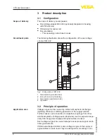
Page 6: ...cted side 2 Screw for carrier rail fastening 3 Terminals In unprotected side 4 Type label 3 2 Principle of operation Voltage surges can be caused by indirect atmospheric discharges lightning strokes o...

Page 7: ...on ISO 4180 The packaging of standard instruments consists of environment friendly recyclable cardboard For special versions PE foam or PE foil is also used Dispose of the packaging material via spec...

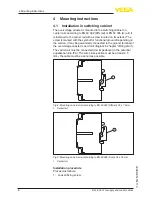
Page 8: ...nctional ground Depending on the version it may be galvanically connected to the ground terminal of the overvoltage arrester see circuit diagram in chapter Wiring plan The carrier rail must be connect...

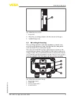
Page 9: ...when mounting that the cable glands point downward Thus avoids water ingress The carrier rail inside the housing is galvanically connected to the ground terminal outside on the housing For this functi...

Page 10: ...nting instructions B 61 300 For supply and control cables 40488 EN 161114 1 2 3 4 OUT IN IP 20 Fig 6 Mounting in plastic housing 1 Overvoltage arrester 2 PE terminal 3 Pressure compensation 4 Ground t...

Page 11: ...ground for the metal housing Note Install a separating facility for the instrument which is easy to access The separating facility must be marked for the instrument IEC EN 61010 5 2 Connection steps f...

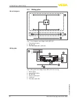
Page 12: ...rrester B61 300 1 Overvoltage arrester 2 PE terminal 3 Potential equalization plant side B61 300 OUT IN IP 20 max 300VAC 0 5A L1 N L1 N 2 3 6 5 4 1 L1 N PE Fig 8 Wiring plan overvoltage arrester B61 3...

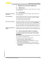
Page 13: ...available in the English language The service is free only standard call charges are incurred Depending on the reason for the fault and the measures taken the steps described in chapter Set up may hav...

Page 14: ...arable WEEE directive 2002 96 EG This instrument is not subject to the WEEE directive 2002 96 EG and the respective national laws Pass the instrument directly on to a spe cialised recycling company an...

Page 15: ...ng Housing material Plastic PPE Weight approx 175 g 0 385 lbs Electrical characteristics1 Operating voltage 100 300 V AC DC Max permissible current 0 5 A Internal resistance 0 01 Response voltage 500...

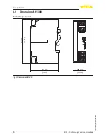
Page 16: ...16 8 Supplement B 61 300 For supply and control cables 40488 EN 161114 8 2 Dimensions B61 300 Overvoltage arrester 84 mm 3 31 52 mm 2 05 25 mm 0 98 Fig 9 Dimensions B61 300...

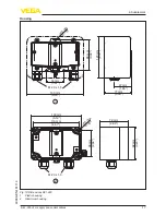
Page 17: ...EN 161114 Housing 5 5 m m 0 22 86 mm 3 39 120 mm 4 72 160 mm 6 30 77 mm 3 03 47 mm 1 85 50 mm 1 97 4 5 m m 0 18 82 mm 3 23 68 mm 2 68 72 mm 2 84 130 mm 5 12 116 mm 4 57 M 20 x 1 5 M 20 x 1 5 1 2 Fig...

Page 18: ...18 Notes B 61 300 For supply and control cables 40488 EN 161114...

Page 19: ...19 Notes B 61 300 For supply and control cables 40488 EN 161114...

Page 20: ...of delivery application practical use and operat ing conditions of the sensors and processing systems correspond to the information available at the time of printing Subject to change without prior n...

Reviews: