background image

5

C

onnecting to power supply

5

.

1

P

reparing the connection

A

lways keep in mind the following safety instructions

:

l

C

onnect only in the complete absence of line voltage

l

I

f overvoltage surges are expected

,

overvoltage arresters

should be installed

I

n hazardous areas you should take note of the appropriate

regulations

,

conformity and type approval certi

cates of the

sensors and power supply units

.

T

wo power supply unit versions are available

.

Y

ou can

nd

detailed information on the power supply in chapter

"

T

echnical

data

"

in the

"

S

upplement

"

.

P

ower supply of

PLICSRADIO T

61

is connected with standard

cable according to the national installation standards

.

S

tandard two

-

wire cable with screening can be used for

connecting the sensors

.

T

he screening is absolutely neces

-

sary to ensure interference

-

free operation with

HART

sensors

.

C

onnect the cable screen on both ends to ground potential

.

I

n

the sensor

,

the screen must be connected directly to the

internal ground terminal

.

T

he ground terminal on the outside of

the sensor housing must be connected to the potential
equalisation

(

low impedance

).

I

f potential equalisation currents are expected

,

the screen

connection on the side of

PLICSRADIO T

61

must be made via

a ceramic capacitor

(

e

.

g

.

1

n

F

,

1500

V

).

T

he low frequency

potential equalisation currents are thus suppressed

,

but the

protective e

ect against high frequency interference signals

remains

.

T

ake note of the corresponding installation regulations for

E

x

applications

.

I

n particular

,

make sure that no potential equal

-

isation currents

ow over the cable screen

.

I

n case of

grounding on both sides this can be achieved by the use of a
capacitor or a separate potential equalisation

.

5

.

2

C

onnection steps sensor

P

roceed as follows

:

N

ote safety instructions

T

ake note of safety

instructions for

E

x

applications

S

elect power supply

S

electing connection cable

C

able screening and ground

-

ing

S

elect connection

cable for

E

x applica

-

tions

PLICSRADIO T

61

-

wireless emitting unit

(

single channel

)

15

C

onnecting to power supply

32865

-

EN

-

070801

Summary of Contents for PLICSRADIO T61

Page 1: ...Operating Instructions PLICSRADIO T61 Wireless Gateway wireless emitting unit single channel Signal conditioning instruments and communication in out...

Page 2: ...4 Packaging transport and storage 11 4 Mounting 4 1 General instructions 12 4 2 Mounting preparations 12 4 3 Mounting steps 13 5 Connecting to power supply 5 1 Preparing the connection 15 5 2 Connecti...

Page 3: ...e 33 8 3 Instrument repair 35 9 Dismounting 9 1 Dismounting steps 36 9 2 Disposal 36 10 Supplement 10 1 Technical data 37 10 2 Dimensions 41 10 3 Industrial property rights 44 10 4 Trademark 44 PLICSR...

Page 4: ...by them 1 3 Symbolism used Information tip note This symbol indicates helpful additional information Caution If this warning is ignored faults or malfunc tions can result Warning If this warning is ig...

Page 5: ...perating instructions manual may be carried out only by personnel authorised by the manufacturer Arbitrary conversions or modi cations are explicitly forbidden 2 3 Warning about misuse Inappropriate o...

Page 6: ...y Industrial areas LVD EN 61010 1 2001 safety regulations for electrical measurement control and laboratory instruments part 1 Gerneral requirements PLICSRADIO T61 is designed for use in an industrial...

Page 7: ...continuously improving company environmental protection The environment man agement system is certi ed according to DIN EN ISO 14001 Please help us ful l this obligation by observing the environ menta...

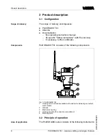
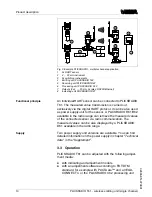
Page 8: ...e following components 5 1 2 3 4 Fig 1 PLICSRADIO T61 1 Housing cover optionally available with window for indicating and adjust ment module 2 Antenna 3 Electronics housing 4 Housing socket with conne...

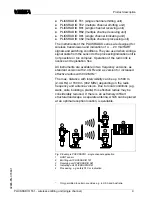
Page 9: ...uency versions as standard version with 2 4 GHz and as version for increased e ective radius with 902 MHz 1 The max distance with intervisibility can be up to 500 m 2 4 GHz or 1600 m 902 MHz depending...

Page 10: ...the sensor A PLICSRADIO R61 R62 available in the radio range can retrieve the measured values of the connected sensor via radio communication The measured values can be also displayed by a PLICSRADIO...

Page 11: ...es Transport must be carried out under consideration of the notes on the transport packaging Nonobservance of these instruc tions can cause damage to the device The delivery must be checked for comple...

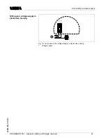
Page 12: ...le obstacles a remote antenna with a 3 m cable is optionally available for standard versions Use the recommended cables see chapter Connecting to power supply and tighten the cable gland You can give...

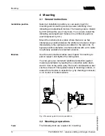
Page 13: ...1 Mark the holes according to the following drilling template 2 Depending on the mounting surface fasten the wall mounting plate with 4 screws 90mm 3 35 64 R3 5mm 9 64 3mm 1 8 70mm 2 3 4 8mm 5 16 93mm...

Page 14: ...arning The four screws for the socket housing must only be hand screwed A torque 5 Nm can damage the wall mounting plate 14 PLICSRADIO T61 wireless emitting unit single channel Mounting 32865 EN 07080...

Page 15: ...st be connected directly to the internal ground terminal The ground terminal on the outside of the sensor housing must be connected to the potential equalisation low impedance If potential equalisatio...

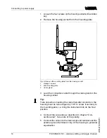
Page 16: ...ke note when inserting the cable that after connection the housing must be turned again by 180 to screw it securely to the mounting plate i e bring the instrument into its the nal position 4 Connect t...

Page 17: ...emove the terminal cover by loosening the xing screw 4 Loosen compression nut of the cable entry 5 Remove approx 10 cm 4 in of the cable mantle strip approx 1 cm 0 4 in insulation from the ends of the...

Page 18: ...on them 11 Tighten the compression nut of the cable entry The seal ring must completely encircle the cable 12 Insert and screw terminal cover 13 If an indicating and adjustment module is installed ins...

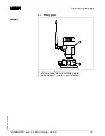
Page 19: ...tage and sensor supply 1 Electronics housing with terminals for voltage supply 2 Socket housing with terminals for sensor connection Overview PLICSRADIO T61 wireless emitting unit single channel 19 Co...

Page 20: ...for the connected sensors This mode is for connection of pressure transmitters without separate supply voltage sensors in two wire version l In the passive mode the sensors are not powered only the m...

Page 21: ...nnection of the voltage supply in electronics housing 1 Voltage supply Wiring plan voltage supply in electronics housing PLICSRADIO T61 wireless emitting unit single channel 21 Connecting to power sup...

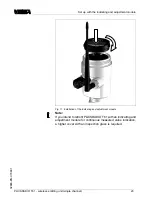
Page 22: ...pt the power supply Proceed as follows 1 Unscrew the housing cover 2 Place the indicating and adjustment module in the desired position on the electronics you can choose any one of four di erent posit...

Page 23: ...o retro t PLICSRADIO T61 with an indicating and adjustment module for continuous measured value indication a higher cover with an inspection glass is required PLICSRADIO T61 wireless emitting unit sin...

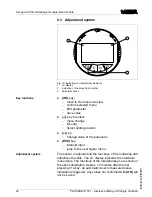
Page 24: ...jump to the next higher menu The sensor is adjusted via the four keys of the indicating and adjustment module The LC display indicates the individual menu items The functions of the individual keys ar...

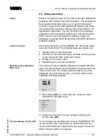
Page 25: ...s well as the instrument TAG instrument name l Enquiry of the sensor input l Establishment of a radio connection The measured value indication displays the digital indication value the measurement loo...

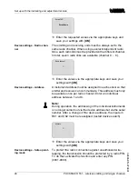
Page 26: ...channel Enter an individual address between 1 and 6 Note During operation the addressing of the individual instruments is no longer carried out via the device address but via the serial number After...

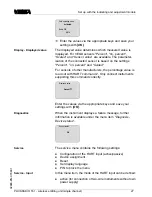
Page 27: ...ed value Percent Enter the values via the appropriate keys and save your settings with OK When the instrument displays a failure message further information is available under the menu item Diagnosis...

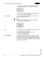
Page 28: ...Reset now In the menu item Info the following information is available l Sensor type and serial number l Date of manufacture and software version l Date of last change using PC l Features of PLICSRAD...

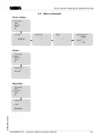
Page 29: ...fe operating mode Activated Radio PIN 1234 Display Device settings Display Diagnostics Service Info Displayed value Percent Diagnostics Device settings Display Diagnostics Service Info Sensor status O...

Page 30: ...settings Display Diagnostics Service Info Sensor type PLICSRADIO xx Serial number 12345678 Date of manufacture 03 February 2004 Software version 1 11 00 Last change using PC 26 September 2004 Device c...

Page 31: ...the PC is carried out via the USB interface The parameter adjustment of a connected VEGA HART sensor can be also carried out via this connection Further information is speci ed in the operating instru...

Page 32: ...roject documentation A DTM licence for the appropriate instrument family can be purchased from the responsible VEGA agency Note To ensure that all instrument functions are supported you should always...

Page 33: ...PC with the PACTware and the suitable DTM In many cases the causes can be determined in this way and faults can be recti ed However if these measures are not successful call the VEGA service hotline...

Page 34: ...ate Wait until software update is nished Carry out another software update E042 l Hardware error with selfcheck Send instrument for repair E053 l Sensor measuring range not read correctly HART communi...

Page 35: ...t the repair quickly and without having to call back for needed information l Print and ll out one form per instrument l Clean the instrument and pack it damage proof l Attach the completed form and i...

Page 36: ...irective 2002 96 EG and the respective national laws in Germany e g ElektroG Pass the instrument directly on to a specialised recycling company and do not use the municipal collecting points These may...

Page 37: ...er supply unit 24 V version 9 6 48 V DC 24 42 V AC 115 230 V version 90 253 V AC 50 60 Hz max power consumption depending on the version of the power supply unit 24 V version 5 3 VA 3 5 W 115 230 V ve...

Page 38: ...na gain standard antenna Standard version 4 dBi Version increased range 1 3 dBi Indicating and adjustment module Power supply and data transmission through PLICSRADIO via gold plated sliding contacts...

Page 39: ...7 Aluminium housing IP 66 IP 672 Overvoltage category III Protection class depending of the power supply unit version 24 V version II 115 230 V version I Electrical separating measures Reliable separa...

Page 40: ...DIP Radio approvals Standard version FCC ID OUR 24xSTREAM Version increased range FCC ID OUR 9xSTREAM IC Industry Canada Standard version 4214A 12008 Version increased range 4214A 9xSTREAM Supplement...

Page 41: ...84 mm 3 5 16 M20x1 5 NPT M20x1 5 NPT M20x1 5 NPT Fig 14 Electronics housing the height of the plastic housing increases by 11 mm 0 43 in with integrated PLICSCOM and of the Alu housing by 9 mm 0 35 i...

Page 42: ...with connection compartment 90mm 3 35 64 110mm 4 21 64 66mm 2 19 32 59mm 2 21 64 Fig 15 Housing socket with connection compartment Supplement 42 PLICSRADIO T61 wireless emitting unit single channel 3...

Page 43: ...m 2 19 32 138 mm 5 7 16 19 mm 3 4 59mm 2 21 64 max 50mm 2 31 32 250mm 9 27 32 3 2 1 Fig 16 Remote antenna 1 Antenna 2 Strap for tube mounting 3 Antenna cable 3 m Supplement PLICSRADIO T61 wireless emi...

Page 44: ...oduits VEGA sont globalement prot g es par des droits de propri t intellectuelle Pour plus d informations on pourra se r f rer au site http www vega com VEGA lineas de productos est n protegidas por l...

Page 45: ...Supplement PLICSRADIO T61 wireless emitting unit single channel 45 32865 EN 070801...

Page 46: ...Supplement 46 PLICSRADIO T61 wireless emitting unit single channel 32865 EN 070801...

Page 47: ...Supplement PLICSRADIO T61 wireless emitting unit single channel 47 32865 EN 070801...

Page 48: ...om www vega com ISO 9001 All statements concerning scope of delivery application practical use and operating conditions of the sensors and processing systems correspond to the information avail able a...

Reviews: