


63138-US-200110
47
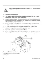
5.4 Pneumatic Switching Facility Connection
These instructions apply to the SHLD 2 source holders with a pneumatic
switching mechanism. Optional position switches signal the switching status of
the source holder
.
Using position switches is recommended
.
They give reliable
feedback and indicate if the switching mechanism has really reacted to the
pneumatic switching impulse
.
Potential Equalization
The terminal box of the position switches is mounted on the pneumatic switching
mechanism. In the terminal box, you can connect a signal line for a PLC/DCS to
the terminals.
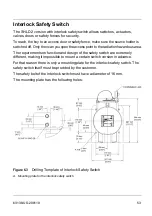
Connect the position switches according to Figure 5.1. Take note of the general
installation regulations. As a rule, connect the SHLD 2 to vessel ground (PA), or in
case of plastic vessels, to the next ground available. Inside the housing there is a
ground terminal. On the outside of the lower housing part, there is an additional
hole for a grounding screw. This connection drains off electrostatic charges
.
Connection Cable
The instrument is connected with standard two-wire cable without screen.
Use cable with round cross-section. A cable outer diameter of 5 … 10 mm (0.2 …
0.39 in) ensures the cable gland is sealed. If you are using cable with a different
diameter or cross-section, exchange the seal or use a suitable cable gland.
As an alternative you can insert the connection cable with conduit pipe connections
.
Do not connect the position switches unless there is a complete
absence of line voltage.
If over-voltage surges are expected, install over-voltage arresters.
!
CAUTION
Summary of Contents for SHLD 2
Page 1: ...Operating Instructions SHLD 2 Source Holder Document ID 63138 Radiometric...
Page 2: ......
Page 8: ...6 63138 US 200110 NOTES...
Page 12: ...10 63138 US 200110 NOTES...
Page 26: ...24 63138 US 200110 NOTES...
Page 42: ...40 63138 US 200110 NOTES...
Page 56: ...54 63138 US 200110 NOTES...
Page 68: ...66 63138 US 200110 NOTES...
Page 78: ...76 63138 US 200110 9 2 Dimensions Figure 9 7 Source Holder SHLD 2 Standard Version...
Page 79: ...63138 US 200110 77 Figure 9 8 SHLD 2 Beam Angles Figure 9 9 SHLD 2 Height for Source Exchange...
Page 80: ...78 63138 US 200110 Figure 9 10 Source Holder SHLD 2 with Limit Switch...
Page 81: ...63138 US 200110 79 Figure 9 11 Source Holder SHLD 2 with Interlock Safety Switch...
Page 82: ...80 63138 US 200110 Figure 9 12 Source Holder SHLD 2 with Air Actuator...
Page 83: ...63138 US 200110 81 Figure 9 13 Source Holder SHLD 2 with Air Actuator and Limit Switch...
Page 84: ...82 63138 US 200110 Figure 9 14 Source Holder SHLD 2 Explosion Proof with Limit Switch...
Page 86: ...84 63138 US 200110 NOTES...
Page 87: ......


